| CPC E05B 17/22 (2013.01) [E05B 15/101 (2013.01); E05B 47/0012 (2013.01); E05B 2047/0058 (2013.01)] | 7 Claims |

|
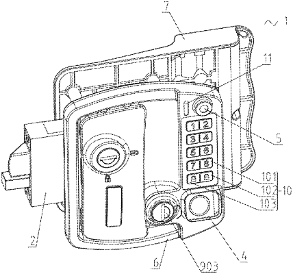
1. An intelligent lock for a recreational vehicle, comprising a recreational vehicle lock body, wherein a lock device is arranged on one side of the recreational vehicle lock body; an electrical control device is arranged in the recreational vehicle lock body; the recreational vehicle lock body is provided with a fingerprint recognition module with an inclination angle; an electronic peep hole capable of observing an external situation is arranged on one side of the fingerprint recognition module; the electrical control device is electrically connected to the fingerprint recognition module and the electronic peep hole; and the electrical control device is connected to the lock device;
wherein the recreational vehicle lock body comprises an outer shell, an inner shell, and a handle assembly; the outer shell is detachably fastened and connected to the inner shell; the lock device is located on a back surface of the outer shell; and the handle assembly is arranged on the outer shell and the inner shell;
wherein the lock device comprises a bevel spring bolt, a lock bar, a spring, a connecting rod, and a double locking assembly; the bevel spring bolt capable of extending and retracting laterally and the lock bar are arranged in the outer shell; the lock bar is located on one side of the bevel lock bar; a tail end of the bevel spring bolt resists against and is provided with the spring, so that the spring pushes the bevel spring bolt to extend outwards; the double locking assembly is arranged on a rear side of the lock bar; the double locking assembly is movably connected to the lock bar through the connecting rod; and the bevel spring bolt is laterally movably connected to the handle assembly;
wherein a diamond-shaped limiting block is arranged in the outer shell; a 7-shaped gap is arranged on a side end surface of the bevel spring bolt; an inverted 7-shaped gap with an avoiding slot is arranged on a side end surface of the lock bar; and when the double locking assembly is locked to push the lock bar to an extended position, two ends of the diamond-shaped limiting block are respectively clamped with the 7-shaped gap and the inverted 7-shaped gap so as to prevent the bevel spring bolt and the lock bar from moving; and when the double locking assembly is unlocked, the diamond-shaped limiting block is received in the avoiding slot to release the bevel spring bolt so that the bevel spring bolt can be driven by the handle assembly to retract to a retracted position.
|