| CPC E01B 11/10 (2013.01) [E01B 11/00 (2013.01); E01B 11/16 (2013.01); E01B 11/20 (2013.01); E01B 11/34 (2013.01); E01B 11/38 (2013.01); E01B 31/02 (2013.01)] | 15 Claims |

|
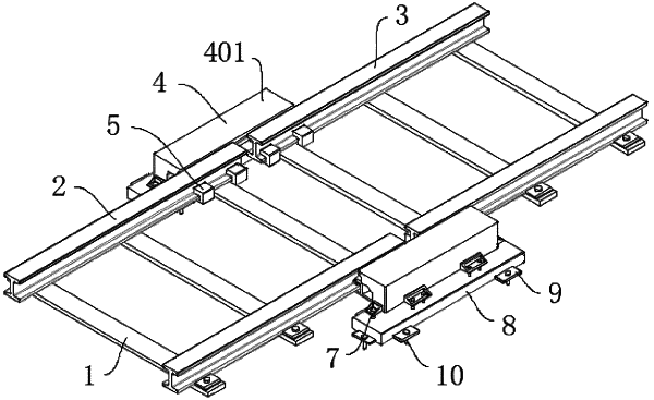
1. A rail temperature expansion joint, comprising: a sleeper, wherein an upper surface of the sleeper is symmetrically mounted with two first rails and two second rails, and the first rail and the second rail on one side are arranged on a same straight line; a gap is arranged between end faces of the first rail and the second rail; adjacent ends of the first rail and the second rail are fastened and positioned by an adjustment component, the adjustment component is fixedly mounted on an embedded part, and the embedded part is located at an outer side of the first rail and the second rail;
the adjustment component comprises a side plate, two sliding grooves, a support rod, a sliding plate, a first pillar, a second pillar, a connecting rod and a buffer spring; the side plate is arranged on the outer side of the first rail and the second rail; an inside of the side plate is provided with the two sliding grooves, an inside of each of the two sliding grooves is fixedly connected with the support rod, an outer peripheral surface of the support rod is sleeved with the sliding plate and the buffer spring; the sliding plate is mounted in an inner cavity of each of the two sliding grooves in a sliding manner, a first end of the buffer spring is fixedly connected inside each of the two sliding grooves, a second end of the buffer spring abuts against the sliding plate, and an outer side surface of the sliding plate is fixedly connected with the first pillar; an outer side surface of the first rail and an outer side surface of the second rail are fixedly connected with the second pillar, and the first pillar and the second pillar at a same height are sleeved with the connecting rod.
|