| CPC B65B 13/16 (2013.01) [B65B 13/025 (2013.01); B65B 13/185 (2013.01); B65B 13/285 (2013.01)] | 7 Claims |

|
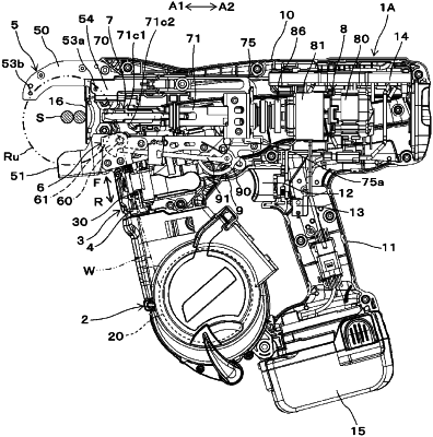
1. A binding machine comprising:
a wire feeding unit configured to feed a wire;
a curl forming unit configured to form a path along which the wire fed by the wire feeding unit is to be wound around an object;
a cutting unit configured to cut the wire wound on the object;
a binding unit configured to twist the wire wound on the object and cut by the cutting unit; and
a transmission unit configured to transmit movement of the binding unit to the cutting unit,
wherein the binding unit comprises a locking member configured to lock the wire, a sleeve configured to actuate the locking member, and a rotary shaft configured to actuate the sleeve,
wherein the transmission unit comprises a displacement member configured to be displaced by movement of the sleeve, and a transmission member configured to transmit movement of the displacement member to the cutting unit,
wherein the cutting unit comprises a movable blade part connected to the transmission member, and
wherein the displacement member is configured to change an amount of movement of the movable blade part in a cutting direction and to change an amount of force imparted by the movable blade part on the wound wire as the displacement member moves within a moving range.
|