| CPC B64C 29/02 (2013.01) [B64C 27/52 (2013.01); B64C 29/0033 (2013.01); B64U 10/25 (2023.01); B64U 30/20 (2023.01); B64U 50/19 (2023.01); B64U 70/80 (2023.01)] | 9 Claims |

|
1. An aerial vehicle comprising:
a fuselage having:
a nose end, and
a tail end;
a first wing member extending from the fuselage in a first direction, the first wing member comprising:
a first drive motor coupled to a first rotor,
a second drive motor coupled to a second rotor, and
a third drive motor coupled to a third rotor,
wherein, in a second direction perpendicular to the first direction, the first wing member and the third drive motor are positioned between the first drive motor and the second drive motor;
a second wing member extending from the fuselage substantially opposite the first wing member;
a first wing rotation motor coupled to rotate the first wing member about a first axis substantially perpendicular to a fuselage axis extending from the nose end to the tail end;
a second wing rotation motor coupled to rotate the second wing member about a second axis substantially perpendicular to the fuselage axis; and
a controller circuit configured to;
differentially actuate the first motor and the second motor;
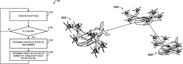
detect a rotation failure of the second wing member based on one or more sensors that generate a signal based on a position of the second wing member; and
responsive to the detecting of the failure, determine a combination of rotor speeds for the first, second, and third rotors and rotation positions for the first wing member that brings about a desired thrust vector and/or moment of torque for the aerial vehicle.
|