| CPC B61L 23/041 (2013.01) [B61L 27/53 (2022.01); G01S 7/4808 (2013.01); G01S 17/89 (2013.01); G06T 7/0004 (2013.01); G06T 2207/10028 (2013.01); G06T 2207/30184 (2013.01)] | 7 Claims |

|
1. A method for in-situ and real-time collection and processing of geometric parameters of railway lines, comprising:
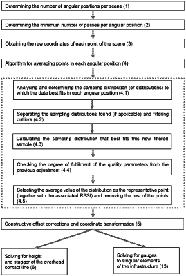
determining a minimum number of a plurality of angular positions per scene necessary, wherein the minimum number of the plurality of angular positions is dependent on both a laser scanner model used and configuration parameters thereof;
determining a minimum number of passes per angular position;
obtaining, by means of a laser scanner mounted on a vehicle, and with the vehicle in a stopped position, raw coordinates of each point of a scene made up by a 2D slice;
obtaining an algorithm for averaging points in each angular position of the plurality of angular positions, eliminating both outliers and ghost points by:
analyzing and determining a sampling distribution or distributions to which a point data fits in each angular position,
separating the sampling distributions found, and filtering any point located at a predetermined distance from a chosen centralization statistic, wherein said predetermined distance is defined based on a margin of +/−“n” times the dispersion statistic selected, “n” being an integer,
calculating the sampling distribution that best fits a new filtered sample, setting minimum quality parameters of the fit in advance,
checking a degree of fulfilment of the quality parameters from the previous fit and, when minimum requirements are exceeded, selecting an average value distance of this distribution together with an associated RSSI thereof as a representative point and removing the rest of the points;
conducting constructive offset corrections of the laser scanner generating the 2D slice, and coordinate transformation, wherein an X-axis is located on a middle rolling plane, and a Y-axis starts from the axis of the track and is perpendicular to the middle rolling plane;
applying either steps to solve for height and stagger of an overhead contact line, or steps to solve gauges to specific elements of the infrastructure,
wherein the steps to solve for height and stagger of the overhead contact line comprises the following steps:
reducing the amount of points to be analyzed within a segment, restricting an area to one region of interest (ROi) defined dynamically according to limit requirements for height and stagger;
spatial grouping or clustering of the points that make up one or two contact wires, using an algorithm to do so that can be set depending on the physical features and constructive limits thereof;
dividing the clusters from the previous step into subgroups of points that give rise to one or two contact wires, and establishing (i) a minimum and maximum threshold of points which define the potential thereof for representing one or two contact wires, and (ii) criteria for dividing the clusters from the previous step depending on the number of points making them up;
spatial weighing of the points contained in the subgroups from the previous step based on the parameter indicating the power of the intensity reflected, and as a result, a point in a “virtual” position is obtained, which is weighted based on the RSSI of the original points;
final filtering of virtual candidate points, selecting as contact wire or wires in the case of lines with double contact wire, those of lowest and of highest stagger;
synchronizing these specific and static measurements of the height and stagger of the contact wire or wires, with a rest of the parameters collected by auxiliary sensors, and
wherein the steps to solve for gauges to specific elements of the infrastructure comprises the following steps of:
reducing the amount of points to be analyzed within a railway line segment, restricting the area to one region of interest (ROI) defined dynamically according to geometric requirements of the specific element of the railway infrastructure;
spatial grouping or clustering of points that could potentially make up part of the specific element;
determining a minimum distance from an origin of coordinates of a reference system;
synchronizing these specific and static measurements of minimum distances to specific elements of the infrastructure, with the rest of the parameters collected by the auxiliary sensors.
|