| CPC B60C 11/1353 (2013.01) [B60C 11/0302 (2013.01); B60C 11/0304 (2013.01); B60C 11/0309 (2013.01); B60C 11/1204 (2013.01); B60C 2011/1213 (2013.01); B60C 2011/1361 (2013.01)] | 2 Claims |

|
1. A pneumatic tire comprising:
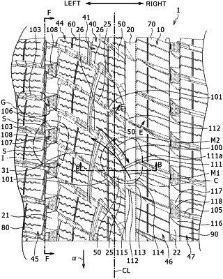
a tread including: a circumferential groove; and a lug groove which is connected to the circumferential groove and which extends from a first side in a tire width direction to a second side;
two first raised portions formed in the circumferential groove, on a groove bottom at positions either side of an end of the lug groove on a side of the circumferential groove;
a second raised portion formed on a groove bottom at a portion of the lug groove on a side of the circumferential groove;
a third raised portion formed at an intersection of the circumferential groove with an extension of the lug groove, on at least a part of a groove bottom of a portion surrounded in three directions by the two first raised portions and the second raised portion, and
a top surface of each of the two first raised portions includes an inclined surface inclined outward in a tire radial direction toward a first land portion next to the circumferential groove on a side with the second raised portion, wherein
in a plan view seen from an outer side in the tire radial direction, each of the two first raised portions has an approximate triangular shape, with a base side of the approximate triangular shape on a wall surface of the first land portion and a vertex is on a side with a second land portion, which is on the other side of the first land portion with the circumferential groove therebetween, and
both ends in a tire circumferential direction of the third raised portion are joined to wall surfaces at ends in the tire circumferential direction of the two first raised portions, one disposed on either side of the third raised portion.
|