| CPC B25J 9/1653 (2013.01) [B24B 51/00 (2013.01); B25J 9/163 (2013.01); B25J 9/1664 (2013.01); B25J 9/1679 (2013.01); B25J 9/1697 (2013.01); B25J 11/0065 (2013.01); B25J 13/085 (2013.01); G06T 1/0014 (2013.01); G06T 7/13 (2017.01); G06T 7/60 (2013.01); G06T 19/00 (2013.01); G06T 2207/10024 (2013.01); G06T 2219/004 (2013.01)] | 20 Claims |

|
1. A method comprising:
during a first time interval:
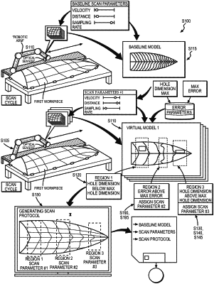
during a first scan of a first workpiece approximating a workpiece geometry, driving a set of actuators to traverse a laser line scanning sensor along a scan axis over the first workpiece loaded into a work zone;
accessing a first series of scan data captured by the laser line scanning sensor, according to a first set of scan parameters, during the first scan;
assembling the first series of scan data into a first virtual model characterized by a first resolution;
accessing a baseline virtual model, of the first workpiece, characterized by a baseline resolution greater than the first resolution;
detecting a first virtual hole, defining absence of scan data, in a first region of the first virtual model;
in response to the first virtual hole defining a first dimension less than a threshold hole dimension, assigning the first set of scan parameters to a first workpiece region of the first workpiece;
detecting a second virtual hole, defining absence of scan data, in a second region of the first virtual model;
confirming absence of a real hole in a second workpiece region of the first workpiece, corresponding to the second virtual hole, based on the baseline virtual model;
in response to the second virtual hole defining a second dimension greater than the threshold hole dimension:
defining a second set of scan parameters associated with a second resolution greater than the first resolution and less than the baseline resolution; and
assigning the second set of scan parameters to the second workpiece region of the first workpiece; and
compiling the first set of scan parameters for the first workpiece region and the second set of scan parameters for the second workpiece region into a scan protocol;
during a second time interval shorter than the first time interval:
during a second scan of a second workpiece approximating the first workpiece geometry, driving the set of actuators to traverse the laser line scanning sensor along the scan axis over the second workpiece loaded into the work zone according to the scan protocol;
accessing a second series of scan data captured by the laser line scanning sensor, according to the first set of scan parameters while traversing the first workpiece region of the second workpiece;
accessing a third series of scan data captured by the laser line scanning sensor, according to the second set of scan parameters while traversing the second workpiece region of the second workpiece;
assembling the second series of scan data and the third series of scan data into a second virtual model of the second workpiece; and
generating a first toolpath representing a trajectory of a sanding head across the second workpiece based on the second virtual model.
|