| CPC B23B 51/0007 (2022.01) [B23B 51/0003 (2022.01); B23B 2251/0825 (2022.01); B23B 2251/087 (2013.01); B23B 2251/12 (2013.01)] | 20 Claims |

|
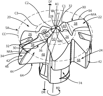
1. A cutting head (20) rotatable about a central axis (A1) in a direction of rotation (RD), the central axis (A1) defining a forward-to-rearward axial direction (DF, DR), and comprising:
a tip portion (22) having an axially forwardmost tip point (NT) contained in the central axis (A1) and at least two axially forward-facing front surfaces (26) forming at least one chisel edge (28) extending from or containing the tip point (NT),
the at least one chisel edge (28) having at least two radially outermost chisel endpoints (NRC); and
each front surface (26) having a cutting edge (30) extending radially outwardly from one of the radially outermost chisel endpoints (NRC), and
an intermediate portion (24) having at least two head lands (42) circumferentially alternating with at least two chip evacuation passages (44), each head land (42) having a leading edge (46) extending axially rearwardly from the tip portion (22), and each chip evacuation passage (44) having a head flute (48) extending axially rearwardly from the tip portion (22) and intersecting one of the leading edges (46),
each leading edge (46) having an axially forwardmost endpoint (NFA), and the at least two axially forwardmost endpoints (NFA) defining an imaginary cutting circle (CC) having a cutting diameter (DC) and a center coincident with the central axis (A1),
wherein:
the at least two cutting edges (30) are contained in an imaginary three-dimensional annular ring surface (SA) exhibiting circular symmetry about the central axis (A1),
in a cross-section taken in a first imaginary radial plane (PR1) containing the central axis (A1) and intersecting the imaginary annular ring surface (SA), the imaginary annular ring surface (SA) forms two imaginary radial cutting profiles (PRC), each imaginary radial cutting profile (PRC) including consecutively radially outward extending first, second, and third cutting profile portions (PCP1, PCP2, PCP3),
each first cutting profile portion (PCP1) has a first radially innermost endpoint (NRI1) and a first radially outermost endpoint (NRO1), and extends radially outward and axially rearward away from the central axis (A1),
each second cutting profile portion (PCP2) has a second radially innermost endpoint (NR12) and a second radially outermost endpoint (NRO2), and includes curved first and second concave sub-portions (CCV1, CCV2) spaced apart by a curved first convex sub-portion (CVX1),
the entire second concave sub-portion (CCV2) is located radially outward of, and axially rearward of, the entire first concave sub-portion (CCV1),
a first imaginary straight line (L1) tangential to any point along one of the second cutting profile portions (PCP2) is either perpendicular to the central axis (A1) or inclined radially outward and axially rearward away from the central axis (A1),
each cutting edge (30) has a radially inner secondary cutting-edge portion (32), and a primary cutting-edge portion (34) extending radially outwardly either directly from said secondary cutting-edge portion (32) or via a transitional cutting-edge portion (36),
each front surface (26) includes a primary and secondary relief surfaces (38, 40) adjacent its associated primary and secondary cutting-edge portions (34, 32), respectively,
each primary cutting-edge portion (34) is formed at the intersection of one of the head flutes (48) and one of the primary relief surfaces (38),
a primary rake surface (52) is disposed on each head flute (48) adjacent the associated primary cutting-edge portion (34),
in a cross-section taken in a first transverse plane (PT1) parallel to the central axis (A1) and intersecting one of the primary cutting-edge portions (34) at any point along its length, the primary rake surface (52) is inclined at a first axial rake angle (β1) relative to a first imaginary vertical reference line (VL1) parallel to the central axis (A1), and
the first axial rake angle (1) is positive.
|