| CPC B05C 3/20 (2013.01) [B05C 3/18 (2013.01); B05D 1/18 (2013.01); B05D 1/26 (2013.01); B05D 7/146 (2013.01); G03G 15/751 (2013.01); B05D 3/0254 (2013.01)] | 10 Claims |

|
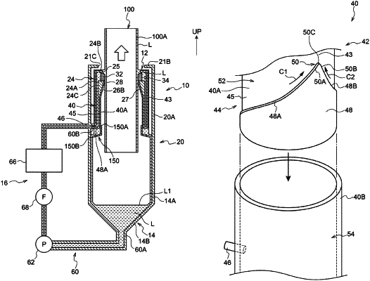
1. A rectifying device comprising:
a first flow channel member that has an annular first flow channel through which a fluid flows in an axial direction, the first flow channel being provided between an inner peripheral wall and an outer peripheral wall;
a second flow channel member that has a second flow channel between the inner peripheral wall and the outer peripheral wall, the second flow channel being provided upstream of the first flow channel in a flowing direction of the fluid and being connected with the first flow channel along an entire circumference;
an inflow section that is provided at the second flow channel member and that allows the fluid to flow into a circumferential area of the second flow channel located away from the first flow channel in the axial direction;
a first guide wall that is provided within the second flow channel at a position located away from the inflow section in a circumferential direction and that guides the fluid flowing toward a first side in the circumferential direction through the second flow channel toward the first flow channel; and
a second guide wall that is provided within the second flow channel at a position adjacent to the first guide wall in the circumferential direction, the second guide wall guiding the fluid flowing toward a second side in the circumferential direction through the second flow channel toward the first flow channel and being disposed in a direction intersecting the first guide wall,
wherein an angle formed between lines that connect a connection end to a point on the first guide wall and a point on the second guide wall that are located at ¼ of a height from the connection end to a lower end of the inflow section is set to 40° or smaller, the connection end being where the first guide wall and the second guide wall connect with each other.
|