| CPC A47L 7/0095 (2013.01) [B24B 7/06 (2013.01); B24B 7/10 (2013.01); B24B 27/0069 (2013.01); B24B 27/0076 (2013.01); B24B 39/065 (2013.01); B24B 41/068 (2013.01); B24B 55/04 (2013.01); B24B 55/06 (2013.01); B24B 9/10 (2013.01); B24B 27/0023 (2013.01); B24B 41/053 (2013.01)] | 16 Claims |

|
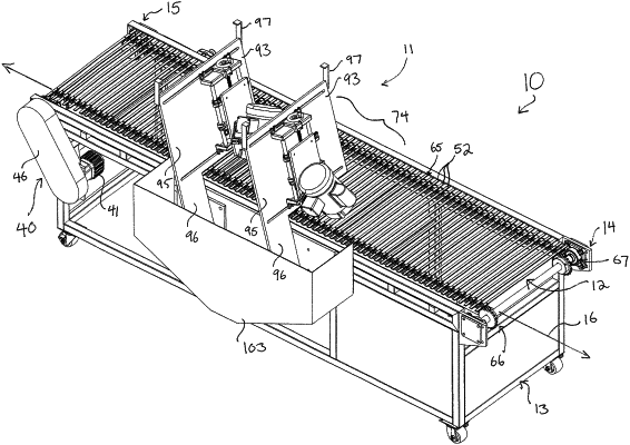
1. A machine for processing a screen printing frame, the machine comprising:
an upstream end and an opposed downstream end of a track;
a grinding assembly located between the upstream and downstream locations; and
the grinding assembly includes a first grinder configured to grind a first grinding pattern into the screen printing frame and a second grinder configured to grind a second grinding pattern into the screen printing frame different from the first grinding pattern;
the first grinder is mounted on a first plate for lateral adjustment on a first rail, which first rail is mounted for vertical adjustment on a first bar, which first bar is mounted in first end brackets fixed to a first board set at a first angle;
the second grinder is mounted on a second plate for lateral adjustment on a second rail, which second rail is mounted for vertical adjustment on a second bar, which second bar is mounted in second end brackets fixed to a second board set at the first angle;
the first and second boards each are L-shaped, having a mounting portion and a leg depending downward from the mounting portion behind a far side of the track;
the legs of the first and second boards depend downward into a basin behind the track, wherein the basin includes a vacuum port configured to connect to a vacuum for removing debris falling into the basin;
a hood over the grinding assembly, wherein the hood does not cover a near side of the track opposite the far side so that the screen printing frame may be held and guided through the grinding assembly and under the first and second grinders, but the hood does cover the grinding assembly, the far side of the track, and the basin behind the track;
the first and second grinders are both set at a second angle leaning back toward the downstream end of the track,
the first and second grinders have first and second orientations, respectively, which are opposite to each other; and
the first and second grinders have shafts which terminate in a common lateral location above the track, such that the first and second grinders are configured to grind a same part of the screen printing frame when the screen printing frame moves under the grinding assembly, first forming the first grinding pattern from the first grinder and then the second grinding pattern from the second grinder, the first and second grinding patterns cooperating to form a cross grinding pattern in the screen printing frame.
|