| CPC H01L 24/75 (2013.01) [H01L 24/743 (2013.01); H01L 2224/757 (2013.01); H01L 2224/75901 (2013.01)] | 12 Claims |

|
1. A producing apparatus, comprising:
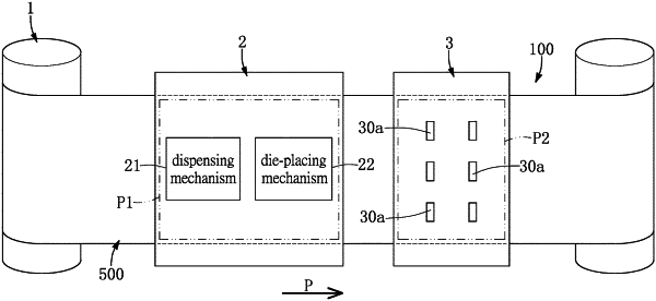
a transporting device defining a predetermined path, wherein the transporting device includes a plurality of carriers and an insulating film that is movable and that carries the plurality of carriers along the predetermined path, and wherein the predetermined path has a pre-bonding region and a die-bonding region that is located at a downstream position relative to the pre-bonding region;
a pre-bonding device arranged corresponding to the pre-bonding region of the predetermined path and including:
a dispenser configured to respectively form a plurality of adhesives onto the carriers that are moving through the pre-bonding region, wherein the carriers are separate from each other; and
a die-placing mechanism disposed adjacent to the dispenser, wherein the die-placing mechanism includes a plurality of catchers configured to respectively hold a plurality of chips, a camera configured to detect positions of the adhesives moving through the pre-bonding region, and a correction unit that is configured to be operated when the catchers hold the chips for adjusting a relative position of the chips, wherein the camera is electrically coupled to the correction unit, the correction unit is configured to adjust positions of the chips held by the catchers according to the positions of the adhesives detected by the camera, and wherein the catchers are configured to synchronously place the chips adjusted by the correction unit onto the adhesives that are moving through the pre-bonding region, so that any one of the chips is able to be detached from the corresponding adhesive; and
a die-bonding device arranged corresponding to the die-bonding region of the predetermined path, wherein the die-bonding device is configured to press against the chips moved through the pre-bonding region and is configured to solidify the adhesives moving through the pre-bonding region, so that any one of the chips is connected to and undetached from the corresponding carrier through the corresponding adhesive.
|