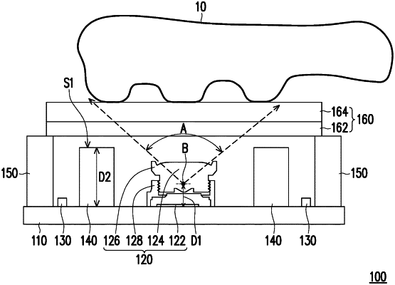
| CPC G06V 40/1324 (2022.01) [G06V 10/147 (2022.01); H04N 23/55 (2023.01)] | 19 Claims |

|
1. An optical fingerprint imaging device, comprising:
a substrate;
an imaging module, disposed on the substrate;
at least one light emitting element, disposed on the substrate and surrounding the imaging module;
a light shielding element, disposed on the substrate and located between the imaging module and the at least one light emitting element;
a case, disposed on an edge of the substrate and surrounding the imaging module; and
a pressing substrate, disposed on the case and covering the imaging module, the at least one light emitting element, and the light shielding element, wherein the optical fingerprint imaging device satisfies conditional expressions of h≤H≤h+(R/tan(θ/2)) and Ravg<S<5Ravg, where h is a height from a field angle origin of the imaging module to an intersection in the imaging module to the substrate, H is a height of the light shielding element at a measurement position, R is a distance from a center of the imaging module to the measurement position of the light shielding element in a horizontal direction, θ is an angle of a field angle of the imaging module, Ravg is an average value of distances from the center of the imaging module to measurement positions of the light shielding element in the horizontal direction, and S is a distance from the center of the imaging module to a center of the at least one light emitting element in the horizontal direction.
|