| CPC G01R 31/42 (2013.01) [G01R 31/343 (2013.01); H02M 1/36 (2013.01); H02M 7/53871 (2013.01); H02M 1/32 (2013.01)] | 16 Claims |

|
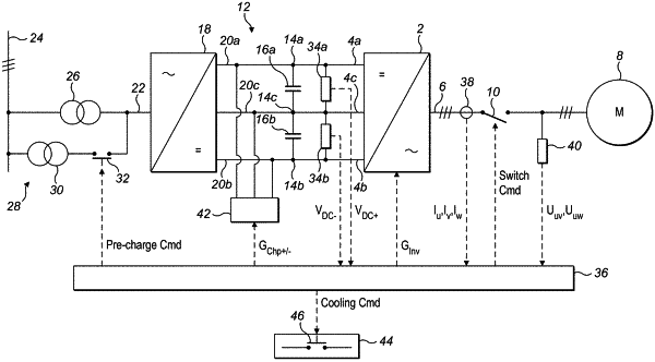
1. A testing process for an electrical system, the electrical system comprising:
a power converter including:
two or more direct current (DC) converter terminals, and
at least one converter leg connected to the DC converter terminals, each converter leg including a plurality of semiconductor switches and an alternating current AC terminal that defines an AC phase of the electrical system and is connectable to a respective AC terminal of an electrical load,
wherein the plurality of semiconductor switches are controllable to put the converter leg in an off-state, or in one of a plurality of on-states that defines a respective voltage level of the converter leg;
a DC bus including:
two or more DC bus terminals, each DC bus terminal being connected to a respective DC converter terminal, and
at least one DC bus capacitor; and
a pre-charge circuit with a contactor;
the testing process being a fully automated testing process, comprising,
conducting a sequence of different diagnostic tests on the electrical system, each diagnostic test testing one of the power converter and the DC bus to determine if it is responding as expected or operating within normal parameters; and
conducting one or more first diagnostic tests where each converter leg is in the off-state, or in the same one of the plurality of on-states, each first diagnostic test comprising:
closing the pre-charge contactor for a period of time to supply the DC voltage to the DC bus,
checking the response time of the pre-charge contactor by measuring the time between a close signal being initiated and a feedback signal confirming the pre-charge contactor has closed being received,
generating a fault signal if the measured time is greater than an expected response time; and
measuring a DC bus voltage while a DC voltage is supplied to the DC bus for a period of time, and generating a fault signal if the measured DC bus voltage does not exceed a first expected DC bus voltage.
|