US 11,781,894 B2
Fluid monitoring module arrangements
Michael D. Bestic, Sagamore Hills, OH (US); David J. Hasak, Concord, OH (US); Bryan S. Reiger, Willowick, OH (US); Andrew Creque, Macedonia, OH (US); Marius O. Stroescu, Mayfield Hts., OH (US); William Michael Ponikvar, Sagamore Hills, OH (US); Cal R. Brown, Lyndhurst, OH (US); Matthew R. Dixon, Parma, OH (US); Joshua Webb, Stow, OH (US); Theodore J. Gausman, Lyndhurst, OH (US); Michael Whisler, Southington, OH (US); Randy Rieken, Littleton, CO (US); Robert Bianco, Columbia Station, OH (US); and Andrew P. Marshall, University Heights, OH (US)
Assigned to Swagelok Company, Solon, OH (US)
Filed by Swagelok Company, Solon, OH (US)
Filed on Dec. 17, 2020, as Appl. No. 17/124,968.
Application 17/124,968 is a continuation of application No. 16/573,289, filed on Sep. 17, 2019, granted, now 10,890,474.
Claims priority of provisional application 62/895,115, filed on Sep. 3, 2019.
Claims priority of provisional application 62/844,399, filed on May 7, 2019.
Claims priority of provisional application 62/844,390, filed on May 7, 2019.
Claims priority of provisional application 62/844,383, filed on May 7, 2019.
Claims priority of provisional application 62/775,066, filed on Dec. 4, 2018.
Claims priority of provisional application 62/732,848, filed on Sep. 18, 2018.
Prior Publication US 2021/0102826 A1, Apr. 8, 2021
This patent is subject to a terminal disclaimer.
Int. Cl. G01F 1/88 (2006.01); G01F 1/40 (2006.01); G01F 1/36 (2006.01); G08C 17/02 (2006.01)
CPC G01F 1/88 (2013.01) [G01F 1/363 (2013.01); G01F 1/40 (2013.01); G08C 17/02 (2013.01)] 19 Claims
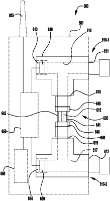
OG exemplary drawing
 
1. A flow sensing device comprising:
a first body member defining an inlet port, an upstream sensor port, and a first connecting port;
a second body member defining an outlet port, a downstream sensor port, and a second connecting port;
a flow restricting element defining a flow restricting passage and including a first end connection coupled to the first connecting port and a second end connection coupled to the second connecting port, such that the flow restricting passage is disposed between the inlet port and the outlet port, and between the upstream sensor port and the downstream sensor port;
a first fluid sensor assembled with the upstream sensor port; and
a second fluid sensor assembled with the downstream sensor port;
wherein the first and second end connections comprise zero clearance connectors that provide for removal and reinstallation of the flow restricting element with the first and second body members without movement of the first and second connecting ports, the zero clearance connectors each including a male threaded connector having an end face groove retaining an O-ring seal.