| CPC F21S 41/29 (2018.01) [F21S 41/27 (2018.01)] | 8 Claims |

|
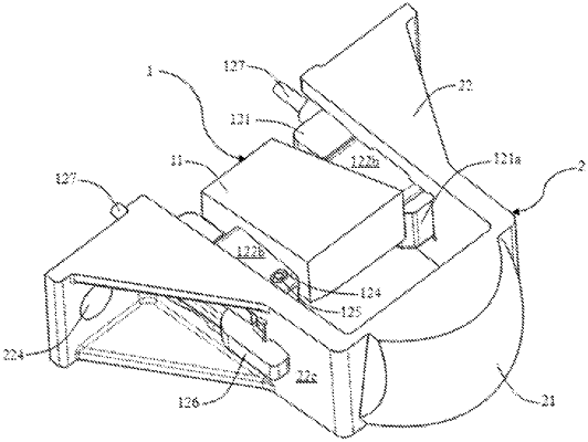
1. A vehicle lamp optical element assembly, comprising a primary optical element assembly (1) and a secondary optical element assembly (2), wherein
the primary optical element assembly (1) comprises a primary optical element (11) and a first support (12) for supporting the primary optical element (11), and
the secondary optical element assembly (2) comprises a secondary optical element (21) and a second support (22) for supporting the secondary optical element (21), wherein
the first support (12) and the second support (22) are connected in a matching manner so as to enable the primary optical element (11) and the secondary optical element (21) to be relatively fixed, wherein
the second support (22) is provided with a slot (221), the first support (12) is matched with the slot (221) in an inserting manner, and the first support (12) is provided with positioning surfaces in contact with surfaces on the inner side of the slot (221);
wherein the secondary optical element (21) is arranged at a front end of the second support (22), and the slot (221) penetrates through a rear end face (22a) of the second support (22) and extends from back to front,
the positioning surfaces of the first support (12) comprise a front positioning surface arranged at a front end face of the first support (12), an upper positioning surface arranged at an upper surface of the first support (12) and a lower positioning surface arranged at a lower surface of the first support (12), wherein
the front positioning surface is in contact with a front surface (221a) on the inner side of the slot (221), the upper positioning surface is in contact with an upper surface (221b) on the inner side of the slot (221), and the lower positioning surface is in contact with a lower surface (221c) on the inner side of the slot (221).
|