| CPC F16B 21/04 (2013.01) [F16C 11/045 (2013.01); F16C 11/10 (2013.01)] | 14 Claims |

|
1. A locking device, comprising a first lock body and a second lock body;
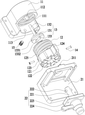
the first lock body comprises an angle rotating disc base, an angle rotating disc and a lock plate, wherein the angle rotating disc is connected with the angle rotating disc base, the angle rotating disc can rotate around its own axis, the lock plate is arranged between the angle rotating disc base and the angle rotating disc; the angle rotating disc base is provided with a first mounting surface for mounting an LED display screen;
the second lock body comprises a fixed base and a spring lock, wherein the spring lock is arranged on the fixed base, the fixed base is provided with a limit surface facing one end face of the angle rotating disc and a second mounting surface for mounting another LED display screen;
the one end face of the angle rotating disc facing the limit surface is provided with a plurality of bevels at intervals along a circumferential direction, and included angles of the plurality of bevels and the first mounting surface are different;
rotating the angle rotating disc can make the limit surface fit with different bevels to adjust the included angle between the first mounting surface and the second mounting surface, and the spring lock and lock plate can be mutually locked to fix the first lock body and the second lock body temporarily; and
the angle rotating disc is movably arranged on the angle rotating disc base, and rotating the angle rotating disc can drive the angle rotating disc to move along the axial direction of the angle rotating disc relative to the angle rotating disc base.
|