| CPC E21B 17/1078 (2013.01) [E21B 4/02 (2013.01); E21B 23/02 (2013.01); E21B 25/02 (2013.01); E21B 25/06 (2013.01); E21B 25/10 (2013.01)] | 8 Claims |

|
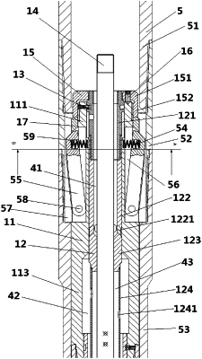
1. A drilling mechanism comprising: a central rod, a fluid channel starting module, an outer barrel, an outer barrel unlocking module, a flow divergent module, and a drill bit,
wherein the central rod extends through an inner cavity of the fluid channel starting module, the outer barrel unlocking module, and the flow divergent module from back to front, the fluid channel starting module is disposed behind the outer barrel and is connected to the outer barrel unlocking module,
the flow divergent module is disposed in front of the outer barrel unlocking module, and a hydraulic motor is connected in front of the flow divergent module,
the outer barrel comprises a driving section, the driving section being a rotor of the hydraulic motor,
an outer wall of the outer barrel is fixedly connected to a centralizer, and a front end of the outer barrel is connected to the drill bit,
the fluid channel starting module comprises a lock body, a locking rod, and a start shear pin,
the locking rod is disposed in the lock body, and the locking rod and the lock body are connected by the start shear pin,
the central rod is disposed in the locking rod, while a sealing section A of the lock body and a sealing section B of the locking rod are in a sealing fit,
the sealing section B is in a sealing fit with the central rod,
a fluid channel A is disposed between the central rod and the locking rod,
an outflow hole A connects the fluid channel A with the outer wall and is disposed behind the sealing section B,
a fluid channel B is disposed between the lock body and the locking rod in front of the sealing section A, and
an outlet of the outflow hole A is disposed at the sealing section A and the front end of the fluid channel A is sealed.
|