| CPC C03B 37/0183 (2013.01) [C03B 37/01291 (2013.01); C03B 37/01294 (2013.01); C03B 37/01446 (2013.01); C03B 37/01453 (2013.01); C03B 37/01473 (2013.01); C03B 37/01493 (2013.01); C03B 37/01853 (2013.01); C03B 37/01869 (2013.01); C03B 37/01892 (2013.01); C03B 37/027 (2013.01); C03B 2201/12 (2013.01); C03B 2201/31 (2013.01); C03B 2203/23 (2013.01); C03B 2203/24 (2013.01)] | 20 Claims |
|
1. A method for manufacturing a preform for optical fibers, comprising the sequential steps of:
i) depositing inner non-vitrified silica layers on the inner surface of a hollow substrate tube by a first inner plasma reaction zone having first reaction conditions, wherein the first inner plasma reaction zone is created in the interior of the hollow substrate tube by means of electromagnetic radiation;
ii) depositing vitrified silica layers inside the hollow substrate tube on the inner surface of the inner non-vitrified silica layers deposited in step i) by a second inner plasma reaction zone having second reaction conditions, wherein the second inner plasma reaction zone is created in the interior of the hollow substrate tube by means of electromagnetic radiation and wherein the vitrified silica layers comprise at least an inner optical cladding layer and an optical core layer;
iii) removing the hollow substrate tube from the vitrified silica layers deposited in step ii) to obtain a deposited tube;
iv) optionally collapsing the deposited tube obtained in step iii) to obtain a deposited rod comprising from its periphery to its center at least one inner optical cladding layer and an optical core;
v) preparing an intermediate cladding layer by the steps of:
depositing outer non-vitrified silica layers on the outside surface of the deposited tube obtained in step iii) or the deposited rod obtained in step iv) with a flame hydrolysis process in an outer reaction zone using one or more glass-forming precursors, and subsequently;
drying and consolidating the outer non-vitrified silica layers into a vitrified fluorine-doped silica intermediate cladding layer; and
in case preceding step iv) was omitted, collapsing the deposited tube with the vitrified intermediate cladding layer;
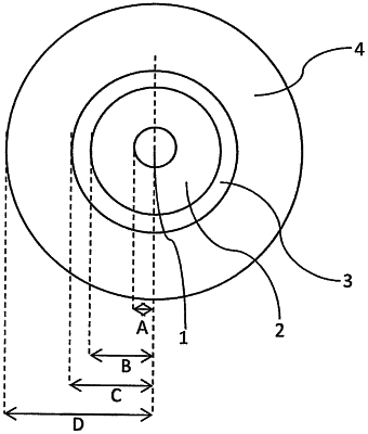
to provide a solid rod comprising from its periphery to its center an intermediate cladding layer, at least one inner optical cladding layer, and an optical core; wherein a fluorine-comprising gas is used during depositing and/or drying and/or consolidating and wherein the ratio between the outer diameter of the intermediate cladding layer (C), which is formed via outside deposition, and the outer diameter of the optical core (A), which is formed via inside deposition, is at least 3.5; and
vi) depositing natural silica on an outside surface of the intermediate cladding layer of the solid rod obtained in step v) by melting natural silica particles in an outer deposition zone to produce an outer cladding whereby a preform is obtained, wherein particles of natural silica having iron impurities of more than 0 ppm iron and less than 0.5 ppm iron are deposited by gravity at a rate between 30 g/min and 150 g/min from a feed pipe moving in translation parallel to the solid rod;
wherein step ii) comprises depositing one or more layers of vitrified fluorine-doped silica having a refractive index difference with undoped silica of between −1×10⁻³ and −10×10−3 to form at least one inner optical cladding layer; and
wherein the absolute difference in refractive index between the preform's intermediate cladding layer and the preform's outer cladding is between 0 and 1×10⁻³.
|