| CPC B65D 41/06 (2013.01) [B65D 50/04 (2013.01); B65D 81/325 (2013.01)] | 26 Claims |

|
1. A cap for sealing a cartridge containing fluid, the cartridge including a cartridge body and a flange extending outwardly from the cartridge body, the cartridge body defining a cartridge outlet, the cap comprising:
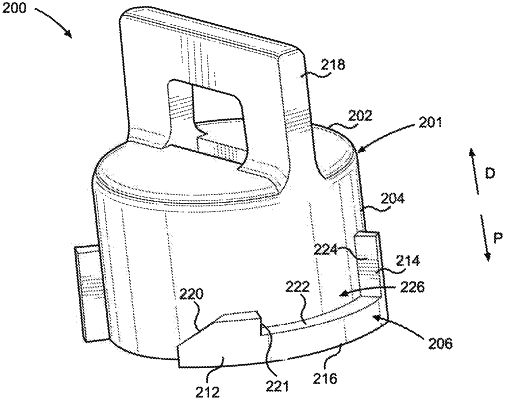
a cap body including a cap wall and an annular wall extending from the cap wall in a proximal direction, the annular wall defining a channel within and including a retention member;
a plug positioned at least partially within the channel of the cap body, the plug being configured to substantially seal the cartridge outlet; and
a biasing member configured to provide a biasing force to bias the cap wall in a distal direction opposite the proximal direction,
wherein the cap is configured to rotatingly transition between a locked position and an unlocked position, wherein in the locked position the retention member is secured to the flange of the cartridge and the plug substantially seals the cartridge outlet, wherein the biasing force provided by the biasing member retains the cap in the locked position, and wherein in the unlocked position the retention member is not secured to the flange,
wherein the cap includes at least one of the following features:
(a) the retention member includes a barb, a stop spaced apart from the barb, and a base extending circumferentially about the annular wall from the bard to the stop, wherein the barb, the stop, and the base define a retention channel and the flange is positioned within the retention channel when the cap is in the locked position;
(b) the retention member is disposed on an outer surface of the annular wall;
(c) the plug includes a plug wall extending substantially perpendicular to the proximal direction and a plug member extending from the plug wall in the proximal direction, wherein the biasing member is positioned between the plug wall and the cap wall and the biasing force biases the cap wall away from the plug wall; and/or
(d) the biasing member is formed on a distal side of a plug wall of the plug such that the plug and the biasing member form a single component.
|