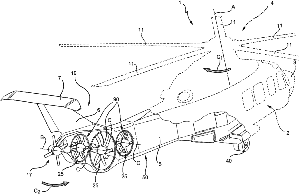
| CPC B64C 27/82 (2013.01) [B64C 27/08 (2013.01); B64C 27/14 (2013.01); B64C 2027/8227 (2013.01); B64C 2027/8254 (2013.01); B64D 2027/026 (2013.01); B64U 10/10 (2023.01)] | 31 Claims |

|
1. A helicopter (1) comprising:
a fuselage (2);
a first main rotor (4), which is adapted to generate, in use, the necessary lift for the flight of said helicopter (1) and to enable the forward/backward, upward/downward and lateral movement of said helicopter (1), and generating, in use, a first torque (C1) on said fuselage (2);
an anti-torque system (10) adapted to generate, in use, a second torque (C2) having a main component in the same or opposite direction with respect to said first torque (C1), so as to control the yaw angle of said helicopter (1); and
a tail portion (5) connected to said fuselage (2);
said tail portion (5) comprising, in turn:
a tail boom (50) connected to said fuselage (2);
a fin (6) protruding from an aft end of said tail boom (50) on the opposite side of said fuselage (2) and transversally with respect to said tail boom (50); and
a tailplane (7) projecting in cantilever fashion on both sides of said fin (6);
said tail boom (50) being adapted to sustain the bending moments and the shear stress generated, in use, by the weight of said fin (6) and said tailplane (7);
characterized in that said anti-torque system (10) integrated with said tail boom (50) and comprises;
an electric power supply unit (15);
at least one second rotor (17) operatively connected to said electric power supply unit (15) and operable by said electric power supply unit (15) so as to rotate with a first variable angular speed; and
at least one third rotor (25) operatively connected to said electric power supply unit (15) and operable by said electric power supply unit (15) so as to rotate with a second variable angular speed;
said tail portion (5) comprising, in turn:
a plurality of walls (35) supporting respective said second and third rotors (17, 25);
a plurality of openings (37) delimited by said walls (35), passing across said tail portion (5) and having sufficient breadth to allow, in use, a correct supply of air to said second and third rotors (17, 25).
|