| CPC B62D 55/10 (2013.01) [B62D 55/065 (2013.01); B62D 55/24 (2013.01); B62D 55/244 (2013.01); B62D 55/26 (2013.01)] | 18 Claims |

|
1. A track assembly to be mounted to a rotatable rear axle of a vehicle, the rotatable rear axle being structured for mechanical attachment of a wheel thereto, comprising:
a frame having a front, a rear, a bottom, a left side, and a right side; the frame including a longitudinally-extending left slide rail positioned at the bottom of the frame, the left slide rail having a bottom surface, a front end having an upward curvature, a rear end and a length; and a longitudinally-extending right slide rail positioned at the bottom of the frame, the right slide rail having a bottom surface, a front end having an upward curvature, a rear end, and a length; wherein the longitudinally-extending left slide rail and the longitudinally-extending right slide rail define an interior space therebetween;
a drive wheel rotationally mounted to the frame for rotation about a drive wheel axis positioned in a vertical drive wheel plane, the drive wheel having a peripheral surface, the drive wheel being structured to be attached to the axle of the vehicle when the wheel is removed, the vertical drive wheel plane being positioned rearwardly from the front end of the left side rail and the front end of the right side rail;
a front idler wheel assembly mounted at the front of the frame for rotation about a front idler wheel assembly axis parallel to the drive wheel axis, the front idler wheel assembly having a peripheral surface;
a rear idler wheel assembly mounted at the rear of the frame for rotation about a rear idler wheel assembly axis parallel to the drive wheel axis, the rear idler wheel assembly having a peripheral surface;
the front idler wheel assembly being mounted in the interior space defined by the longitudinally-extending left slide rail and the longitudinally-extending right slide rail, between the upward curvatures of the front ends thereof, with the peripheral surface of the front idler wheel assembly extending forward of the front ends of the side rails; and
a track having an inner surface facing the drive wheel, and an outer surface opposite the inner surface, the outer surface having a plurality of traction lugs distributed along the outer surface, the track including a plurality of longer transverse reinforcement rods distributed therethrough and a plurality of shorter transverse reinforcement rods distributed therethrough, the shorter transverse reinforcement rods being shorter in length than the longer transverse reinforcement rods, each of the longer and shorter transverse reinforcement rods being aligned along at least a part of its length with at least one of the traction lugs;
the drive wheel, the front idler wheel assembly and the rear idler wheel assembly being positioned relative to the frame to support the track around the drive wheel peripheral surface, the front idler wheel assembly peripheral surface, and the rear idler wheel assembly peripheral surface,
the track being in driving engagement with the drive wheel, and
the track assembly comprising:
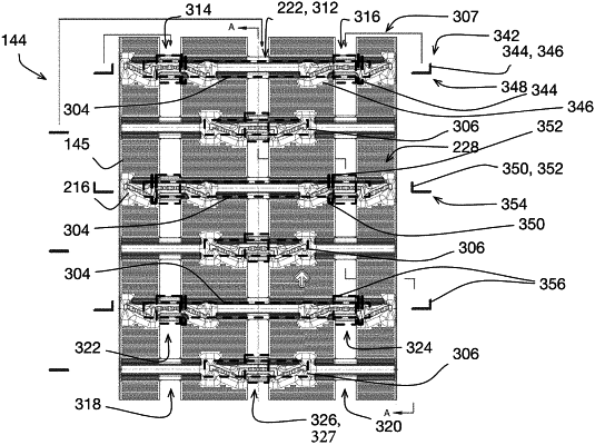
a first plurality of L-shaped clips mounted to the track such that each clip of the first plurality of L-shaped clips passes with each revolution of the track around the frame of the track assembly between the left slide rail and the track, each clip of the first plurality of L-shaped clips having an upstanding L-portion extending from the track toward the frame of the track assembly;
a second plurality of L-shaped clips mounted to the track such that each clip of the second plurality of L-shaped clips passes with each revolution of the track around the frame of the track assembly between the right slide rail and the track, each clip of the second plurality of L-shaped clips having an upstanding L-portion extending from the track toward the frame of the track assembly; and
a third plurality of L-shaped clips mounted to the track over a middle portion of each of the plurality of shorter transverse reinforcement rods such that each clip of the third plurality of L-shaped clips passes with each revolution of the track around the frame of the track assembly between the drive wheel and the track, each clip of the third plurality of L-shaped clips having an upstanding L-portion extending from the track toward the frame of the track assembly; and
at least one of the front idler wheel assembly and the rear idler wheel assembly being selectively movable between a plurality of longitudinally-distributed tension positions to tension the track.
|