| CPC B31B 50/20 (2017.08) [B26D 1/405 (2013.01); B26D 1/435 (2013.01); B26D 5/00 (2013.01); B26D 7/265 (2013.01); B31B 50/022 (2017.08); B31D 1/0043 (2013.01); B42C 7/008 (2013.01); B26D 2007/2664 (2013.01)] | 20 Claims |

|
1. A device for producing book cases (103), box lids or game boards, comprising at least
a first feed mechanism (1) for pre-cut cardboards (101) with a first transport direction (g), in which the pre-cut cardboards (101) are supplied,
a second feed mechanism (2) for blanks to be covered (102, 105) with at least
a second transport direction (b), in which the blanks to be covered (102, 105) are supplied,
a separating mechanism (3) for blanks to be covered (102, 105) and
a cutting mechanism (9) that is arranged downstream of the separating mechanism (3) for blanks to be covered (102, 105) referred to the second transport direction (b) of the blanks to be covered (102, 105),
a glue application mechanism (4) that is arranged downstream of the second feed mechanism (2) for blanks to be covered (102, 105) referred to the second transport direction (b) of the blanks to be covered (102, 105),
a joining mechanism (5) that is arranged downstream of the first feed mechanism (1) for pre-cut cardboards (101), as well as the glue application mechanism (4), referred to the material flow,
a delivery mechanism (6) for pre-cut cardboards (101) lined with blanks to be covered (105), wherein said delivery mechanism is arranged downstream of the joining mechanism (5) referred to the material flow, and
a cutting mechanism (9) that is arranged in the region of the second feed mechanism (2) for blanks to be covered (102, 105) and has at least
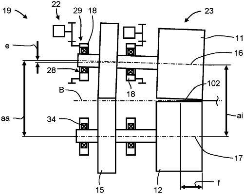
a tool pair (10) that penetrates the transport plane (B) of the blanks to be covered (102, 105) and consists of a rotatable cutting cylinder (11), which has an outer surface area (23) and at least one cutting edge (24) projecting from the outer surface area (23), and a rotatable counterpressure cylinder (12) assigned to the cutting cylinder (11), wherein a first rotational axis (16) of the cutting cylinder (11) and a second rotational axis (17) of the counterpressure cylinder (12) of the tool pair (10) are arranged essentially parallel to one another and jointly arranged essentially transverse to the second transport direction (b) of the blanks to be covered (102, 105),
a tool receptacle with at least one bearing block (13), in which the cutting cylinder (11) and the counterpressure cylinder (12) of the tool pair (10) are accommodated,
a drive connection (14) between the counterpressure cylinder (12) and the cutting cylinder (11) of the tool pair (10),
a variable axial spacing (a, aa, ai) of the first rotational axis (16) of the cutting cylinder (11) from the second rotational axis (17) of the counterpressure cylinder (12) of the tool pair (10),
two bushes (18) of the tool receptacle, each bush with a respective bore (28), in which either the cutting cylinder (11) or the counterpressure cylinder (12) is accommodated and with at least one additional surface area (29), and
a one-sided bearing arrangement of the cylinders (11, 12) in the bearing block (13) of the tool pair (10), wherein the two bushes (18) of the same tool (11, 12) are arranged on the same side of this tool (11, 12),
wherein
the bore (28) of each bush (18) is respectively arranged eccentric to the at least one additional surface area (29) of the same bush (18),
the two bushes (18) respectively are rotatably accommodated in the at least one bearing block (13) with their at least one additional surface area (29) in such a way that a respective change of the rotating position of the bush (18) causes a change in the position of the rotational axis (16, 17) of the respective cutting cylinder (11) or counterpressure cylinder (12) accommodated in the bush (18),
the two bushes (18) assigned to the same cylinder (11, 12) of a tool pair (10) are spaced apart from one another in the axial direction by a distance (h), and
at least one drive element (15) of the drive connection (14) between the counterpressure cylinder (12) and the cutting cylinder (11) of the same tool pair (10) is arranged between the two bushes (18) assigned to this tool pair (10).
|