| CPC B23Q 3/082 (2013.01) [B23Q 3/108 (2013.01); B25B 5/062 (2013.01); B23Q 2240/002 (2013.01); B25B 5/061 (2013.01)] | 9 Claims |

|
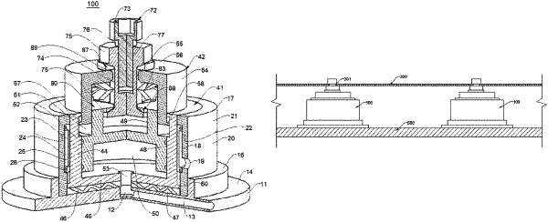
1. A clamping device comprising:
a base, an adjustable assembly, and a clamping head mounted to the base by means of the adjustable assembly,
wherein the base comprises a base plate and an annular outer wall perpendicularly connected to the base plate, and an expansion sleeve is embedded into an inner peripheral face of the outer wall;
the adjustable assembly comprises a lower cavity, an upper cavity and a support cylinder;
the lower cavity comprises an annular enclosure wall and a bottom wall connected to a lower end opening of the enclosure wall, the enclosure wall is slidably fitted in the outer wall of the base and is expandable and pressable against the outer wall by the expansion sleeve, the bottom wall is supported on the base plate in a spaced manner by means of a support member, and a lower fluid chamber is defined therebetween;
the support cylinder comprises a cylindrical portion opening downwards and an annular support wall located on the cylindrical portion; the cylindrical portion is slidably fitted in the enclosure wall of the lower cavity and forms a fluid chamber with the lower cavity in an enclosed manner, the cylindrical portion of the support cylinder is fitted to a lower section of the enclosure wall of the lower cavity, and an outer peripheral face of the support wall of the support cylinder and an upper section of the enclosure wall of the lower cavity are spaced to define an annular space;
the bottom wall is provided with fluid through holes passing through upper and lower surfaces thereof, an upper surface of the base plate has a blind hole formed by recessing, and the blind hole and the fluid through holes are respectively in communication with the lower fluid chamber; a tube hole that is in communication with an outer peripheral face of the base plate and the blind hole is further provided in the base plate, and serves as a passage leading to the fluid chamber so as to adjust a vertical position of the support cylinder by introducing/discharging a fluid;
the upper cavity comprises an annular peripheral wall and a top wall formed extending inwards in a radial direction from an upper edge of the peripheral wall and having a central hole; the peripheral wall of the upper cavity is downwards slidably fitted in the annular space, an inner peripheral face of the upper section of the enclosure wall of the lower cavity is provided with a recessed annular groove, a lower edge of the peripheral wall of the upper cavity has a convex ring that is formed expanding outwards in the radial direction, and the peripheral wall of the upper cavity is limited between two end faces of the annular groove in an axial direction by means of the convex ring thereof;
the clamping head comprises a blind rivet and a locking member; the blind rivet comprises a middle column segment and enlarged portions respectively connected to upper and lower ends of the middle column segment; the locking member is configured to be connectable to an upper end of the blind rivet, and a clamping opening for clamping a part is defined between the locking member and the blind rivet;
the top wall is clamped between the two enlarged portions of the blind rivet, and the middle column segment of the blind rivet movably passes through the central hole; a concave washer is provided between an inner peripheral face of the peripheral wall and an outer peripheral face of the middle column segment, and a laminated spring as an elastic member is provided in the peripheral wall and is elastically supported between the top wall and the concave washer to elastically strut the concave washer and the peripheral wall between the enlarged portion at the lower portion of the blind rivet and the enlarged portion at the upper portion of the blind rivet;
the support wall of the support cylinder is located between the peripheral wall of the upper cavity and the enlarged portion at the lower portion of the blind rivet, and is vertically supported at the lower end of the elastic member;
the diameters of the central hole, an inner hole of the elastic member and an inner hole of the concave washer are all greater than that of the middle column segment;
an upper step surface achieves the transition between the enlarged portion at the upper portion of the blind rivet and the middle column segment, a lower step surface achieves the transition between the enlarged portion at the lower portion of the blind rivet and the middle column segment, and the upper step surface and the lower step surface are both circular conical surfaces or spherical cambered surfaces; the enlarged portion at the upper portion of the blind rivet is supported on the top wall of the upper cavity by means of an upper arcuate washer, and an upper surface of the upper arcuate washer is a circular conical surface or a spherical cambered surface fitted to the upper step surface; and the enlarged portion at the lower portion of the blind rivet is supported below the concave washer by means of a lower arcuate washer, and a lower surface of the lower arcuate washer is a circular conical surface or a spherical cambered surface fitted to the lower step surface.
|