| CPC A61B 6/504 (2013.01) [A61B 5/026 (2013.01); A61B 5/0215 (2013.01); A61B 6/481 (2013.01); A61B 6/507 (2013.01); A61M 5/007 (2013.01); G06T 7/0012 (2013.01); G06T 7/0016 (2013.01); G06T 7/215 (2017.01); G06T 7/62 (2017.01); G06T 17/00 (2013.01); G06T 2207/30048 (2013.01); G06T 2207/30104 (2013.01); G06T 2207/30172 (2013.01); G06T 2210/41 (2013.01)] | 9 Claims |

|
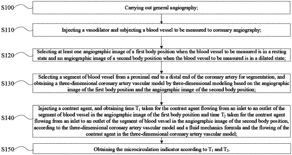
1. A method for calculating a microcirculation indicator based on an image and a pressure sensor comprising:
carrying out general angiography;
injecting a vasodilator and subjecting a blood vessel to be measured to coronary angiography;
selecting at least one angiographic image of a first body position when the blood vessel to be measured is in a resting state and an angiographic image of a second body position when the blood vessel to be measured is in a dilated state;
selecting a segment of blood vessel from a proximal end to a distal end of the coronary artery for segmentation, and obtaining a three-dimensional coronary artery vascular model by three-dimensional modeling based on the angiographic image of the first body position and the angiographic image of the second body position;
injecting a contrast agent, and obtaining time T1 taken for the contrast agent flowing from an inlet to an outlet of the segment of blood vessel in the angiographic image of the first body position and time T2 taken for the contrast agent flowing from an inlet to an outlet of the segment of blood vessel in the angiographic image of the second body position, respectively, according to the three-dimensional coronary artery vascular model and a fluid mechanics formula and the flowing of the contrast agent in the three-dimensional coronary artery vascular model; and
obtaining the microcirculation indicator according to T1 and T2;
wherein the microcirculation indicator comprises: coronary artery microcirculation resistance index IMR;
measuring a coronary artery inlet pressure Pa by the pressure sensor to obtain a pressure drop ΔPi from a coronary artery inlet to a stenosed distal end of the coronary artery in the dilated state;
obtaining the coronary artery microcirculation resistance index IMR according to the coronary artery inlet pressure Pa, pressure drop ΔPi, and T2, wherein the IMR=(Pa−ΔPi)×T2; and
wherein measuring the pressure drop ΔPi from the coronary artery inlet to the stenosed distal end of the coronary artery comprises:
subjecting the three-dimensional coronary artery vascular model to a grid division, with the coronary artery centerline as the longitudinal axis, dividing the grid into m points along the coronary artery centerline, and dividing the cross section corresponding to each point of the coronary artery centerline into n nodes, ΔPi representing the average value of the pressures of all nodes on the cross section of the i-th point on the coronary center line; the pressure drop ΔPi is calculated using the following formula:
 P1 represents the pressure value of the first node on the cross section of the i-th point in the grids of the three-dimensional vascular model, P2 represents the pressure value of the second node on the cross section of the i-th point in the grids of the three-dimensional vascular model, Pn represents the pressure value of the n-th node on the cross section of the i-th point, and both m and n are positive integers;
the pressure value of each node is calculated using the Navier-Stokes equation.
|