| CPC A43C 11/00 (2013.01) [A43C 1/06 (2013.01); A43C 11/16 (2013.01); A43C 11/165 (2013.01); A45C 13/10 (2013.01); A61F 5/0118 (2013.01); A63C 10/06 (2013.01); B65H 75/30 (2013.01); B65H 75/4434 (2013.01); A41F 1/06 (2013.01); A41F 9/025 (2013.01); A45F 3/00 (2013.01); A45F 3/04 (2013.01); A45F 3/16 (2013.01); Y10T 24/21 (2015.01); Y10T 24/2183 (2015.01); Y10T 24/2187 (2015.01); Y10T 24/37 (2015.01)] | 20 Claims |

|
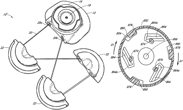
1. A closure system for tensioning a lace, the closure system comprising:
a housing;
a spool rotatably positioned within the housing, the spool being rotatable in a first direction to wind the lace about the spool and being rotatable in a second direction to unwind the lace from about the spool;
a pawl member that includes at least one pawl;
a plurality of teeth configured to engage a distal end of the at least one pawl so that the spool is rotatable in the first direction while substantially impeding the spool from rotating in the second direction; and
a rotatable cover comprising a pawl disengagement tab that extends substantially perpendicular to a surface of the cover and a drive tab formed on the cover, the pawl disengagement tab and drive tab having different shapes and orientations about an inner surface of the cover;
wherein the pawl disengagement tab is configured to engage the distal end of the at least one pawl and disengage the at least one pawl from the teeth when the cover is rotated in the second direction to allow the spool to rotate in the second direction and thereby unwind the lace from about the spool; and
wherein the drive tab is configured to engage the pawl member when the cover is rotated in the first direction to cause the pawl member and spool to rotate in the first direction.
|