| CPC B01D 1/007 (2013.01) [B01D 1/06 (2013.01); B01J 6/008 (2013.01); C07C 273/02 (2013.01); C07C 273/16 (2013.01)] | 20 Claims |

|
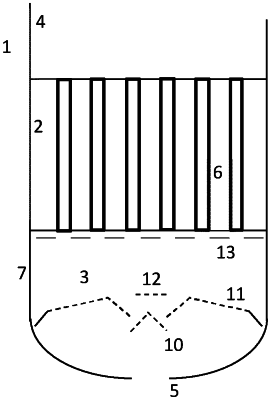
1. A vertical distribution chamber for in an apparatus comprising a first chamber and a second chamber, wherein said apparatus is configured to operate with a bottom-to-top liquid flow, wherein the first chamber comprises a plurality of pipes for guiding a liquid stream from the distribution chamber to the second chamber and each pipe comprises a pipe opening fluidly connected to the distribution chamber, for evenly distributing a liquid stream to the plurality of pipe openings, the distribution chamber comprising:
a body comprising an open circular end, a capped circular end, and a cylindrical wall along a central axis joining the first open circular end and the second capped circular end, wherein:
the cylindrical wall has a same diameter as the open circular end and the capped circular end;
the open circular end is adapted to fit with the first chamber of the apparatus;
one inlet located on the capped circular end of the distribution chamber for feeding the liquid stream into the distribution chamber, wherein the inlet is centered on the central axis of the distribution chamber;
a series of stacked plates comprising at least a first perforated plate, a second perforated plate, and a third perforated plate,
wherein:
the first perforated plate has a shape of a cone pointing towards the open circular end, is centered on and perpendicular to the central axis of the distribution chamber, is located directly above the inlet, a diameter of a base of the cone is 70% to 130% of a diameter of the inlet of the distribution chamber, and wherein the perforations make up from 1 to 10% of a surface of the first perforated plate;
the second perforated plate is a ring-shaped disk-like plate centered on the central axis of the distribution chamber, has an outer diameter of about the diameter of the cylindrical wall and an inner diameter of about the diameter of the base of the cone of the first perforated plate and wherein the perforations make up from 10 to 20% of the surface of the second perforated plate; and
the third perforated plate is a disk with a diameter from 1 to 10 mm smaller than the diameter of the cylindrical wall, and is configured to be positioned from 5 mm to 25 mm directly below the inlets of the plurality of pipes, wherein each perforation in the third perforated plate is configured to align with a pipe opening in the first chamber and each pipe opening from the plurality of pipes of the first chamber has a corresponding perforation in the third perforated plate, each perforation is a circular through-hole and a diameter of each circular through-hole is 30% to 50% of a diameter of a pipe openings.
|