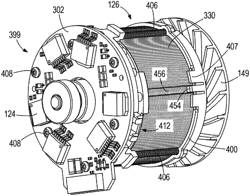
| CPC H02K 7/145 (2013.01) [B23B 45/02 (2013.01); B25B 21/00 (2013.01); B25F 5/008 (2013.01); H02K 3/522 (2013.01); H02K 11/33 (2016.01); H02K 29/08 (2013.01); H02K 2203/06 (2013.01)] | 20 Claims |

|
1. A power tool comprising:
a housing;
a brushless direct current (DC) motor within the housing, wherein the brushless DC motor includes a rotor and a stator, wherein the rotor is coupled to a motor shaft arranged to rotate about a longitudinal axis, the longitudinal axis extending through the motor shaft, and wherein the motor shaft is arranged to produce a rotational output to a drive mechanism;
a metal mounting structure positioned at a first end of the brushless DC motor;
a heat sink positioned at a second end of the brushless DC motor opposite the first end, wherein the brushless DC motor is positioned between the heat sink and the metal mounting structure;
threaded fastening elements securing the heat sink, the brushless DC motor, and the metal mounting structure to each other, wherein the brushless DC motor has an axial length, and the threaded fastening elements extend along the axial length of the brushless DC motor; and
a printed circuit board (PCB) positioned at the second end of the brushless DC motor and secured to the heat sink on a side of the heat sink that is opposite to the brushless DC motor, wherein the PCB includes a Hall sensor, power switching elements, and a through-hole through which the longitudinal axis extends, wherein the power switching elements are flat-mounted to a surface of the PCB that faces a direction opposite to the heat sink and the brushless DC motor.
|