| CPC G01R 21/133 (2013.01) [G01R 31/086 (2013.01); G01R 31/088 (2013.01); H02J 3/00 (2013.01)] | 8 Claims |

|
1. A transformer area identification method of power supply lines in a transformer area for quickly and accurately identifying transformer area power supply line topology to dynamically monitor aging of power supply lines in the transformer area and rapid positioning and troubleshooting of faults in power supply lines of the transformer area, comprising the following steps:
in the transformer area comprising a concentrator connected to a plurality of branch terminals and a plurality of branch power supply lines, each of the plurality of branch power supply lines connected at a starting point of each of the plurality of branch terminals,
the concentrator comprises a master meter and central coordination organization and
each of the plurality of branch terminals comprises a sub-meter, and
each sub-meter comprises an electric meter and a carrier module through which each of the plurality of branch terminals communicates with the central coordination organization of the concentrator,
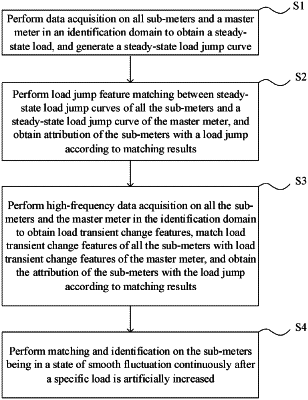
step S1: performing data acquisition on all sub-meters and the master meter in an identification domain to obtain a steady-state load and generating a steady-state load jump curve;
step S2: performing load jump feature matching between steady-state load jump curves of all the sub-meters and a steady-state load jump curve of the master meter to obtain first matching results, and obtaining attribution of the sub-meters with a load jump according to the first matching results; and
step S3: performing high-frequency data acquisition on all the sub-meters and the master meter in the identification domain to obtain load transient change features, matching load transient change features of all the sub-meters with load transient change features of the master meter to obtain second matching results, and obtaining the attribution of the sub-meters with the load jump according to the second matching results, wherein
a process of matching the load transient change features of all the sub-meters with the load transient change features of the master meter in step S3 specifically comprises the following sub-steps;
extracting noise of the sub-meters in smooth fluctuation, superimposing the noise with the load transient change features of jumping sub-meters to calculate first expected load transient change features of the master meter, then fitting and comparing the first expected load transient change features of the master meter with an actual load characteristic curve of the master meter within a period of time centered on a jumping time point to obtain first comparison results, and obtaining the attribution of the jumping sub-meters according to the first comparison results; or
directly ignoring the noise of the sub-meters in smooth fluctuation, superimposing the load transient change features of the jumping sub-meters to calculate second expected load transient change features of the master meter, then fitting and comparing the second expected load transient change features of the master meter with the actual load characteristic curve of the master meter within the period of time centered on the jumping time point to obtain second comparison results, and obtaining the attribution of the jumping sub-meters according to the second comparison results.
|