| CPC G01J 1/44 (2013.01) [G01S 7/4863 (2013.01); G01S 7/4865 (2013.01); G01J 2001/448 (2013.01); G01J 2001/4466 (2013.01); G01S 17/894 (2020.01)] | 5 Claims |

|
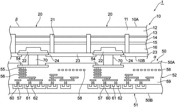
1. A photodetector device, comprising:
an avalanche photodiode array substrate in which a plurality of avalanche photodiodes are two-dimensionally arranged, the avalanche photodiode array substrate being formed from compound semiconductor, the plurality of avalanche photodiodes being connected to a quenching circuit and arranged to operate in a Geiger mode; and
a circuit substrate on which the avalanche photodiode array substrate is mounted,
wherein the circuit substrate includes a plurality of time measurement circuits two-dimensionally arranged in the circuit substrate in correspondence with the plurality of avalanche photodiodes, and a clock driver arranged to supply a clock signal to the plurality of time measurement circuits,
each of the time measurement circuits includes a delay line unit including a delay line constituted by a plurality of delay elements connected in series, and is arranged to acquire, from an operation result to the delay line, time information indicating timing at which a pulse signal is input from a corresponding one of the avalanche photodiodes to a corresponding one of the time measurement circuits,
the delay line unit is arranged to initiate an operation of the delay line in response to input of the pulse signal output from the corresponding avalanche photodiode to the time measurement circuit, and to stop the operation of the delay line in response to input of the clock signal from the clock driver to the time measurement circuit, and is arranged to detect a time interval shorter than a cycle of the clock signal by the operation of the delay line,
wherein each of the time measurement circuits further includes a counter arranged to count the clock signal, and is arranged to acquire, from an operation result of the counter and an operation result of the delay line, time information indicating timing at which the pulse signal is input from the corresponding avalanche photodiode,
wherein the counter is arranged to initiate an operation of the counter in response to stoppage of the operation of the delay line, and to stop the operation of the counter in synchronization with the clock signal from the clock driver,
wherein the circuit substrate includes a memory and a control circuit arranged to control the time measurement circuit for every time measurement circuit,
the control circuit is arranged to reset the corresponding time measurement circuit in response to input of a reset signal to the control circuit, and to stop input of the clock signal to the counter in response to input of a stop signal to the control circuit,
the reset signal and the stop signal are synchronized with the clock signal,
the delay line unit is arranged to store, in the memory, the number of the delay elements which have operated from input of the pulse signal until an input of the clock signal from the clock driver to the time measurement circuit when the pulse signal is output from the corresponding avalanche photodiode after the reset signal is input to the corresponding time measurement circuit, and
the counter is arranged to store, in the memory, the number of the clock signal counted from stoppage of the operation of the delay line until input of the stop signal to the counter.
|