| CPC F16D 66/00 (2013.01) [B60T 8/171 (2013.01); B60T 8/329 (2013.01); F16D 65/123 (2013.01); F16D 65/128 (2013.01); G01P 3/488 (2013.01); B60T 2240/00 (2013.01); F16D 2065/1328 (2013.01); F16D 2066/003 (2013.01)] | 14 Claims |
|
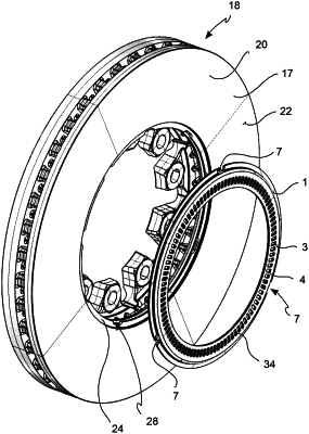
1. An anti-lock sensor ring, comprising:
an annular ring body comprising a flattened exciting portion comprising a plurality of exciting elements suitable to interact with a stationary sensor;
the annular ring body comprising a rotation axis defining an axial direction parallel or coincident with the rotation axis, a radial direction orthogonal to the axial direction, and a circumferential direction orthogonal both to the axial direction and the radial direction;
the flattened portion comprising an external ring radial edge;
a retention mechanism is projecting from the ring radial edge;
the retention mechanism comprises cantilever spring retention clips elastically deformable to snap on a disc brake band retention seat;
the retention mechanism comprises a cantilever support portion;
at least a portion of each of the cantilever spring retention clips is side by side to and spaced apart from the cantilever support portion defining a clamp channel;
each of the cantilever spring retention clips comprising a retention surface;
the cantilever support portion comprising a support surface;
wherein the plane defined by the retention surface and the plane defined by the support surface are facing each other in order to create opposing gripping elements;
wherein the cantilever support portion is a continuous ring partially circumferentially interrupted by ring windows, each ring window comprising a window base disposed close to the flattened exciting portion; and wherein
each of the cantilever spring retention clips extend from the window base with an orthogonal spring arm disposed orthogonal to the flattened exciting portion and a gripping end defining the at least a portion of each of the cantilever spring retention clips disposed side by side to and spaced apart from the cantilever support portion.
|