| CPC F01D 5/186 (2013.01) [F01D 5/147 (2013.01); F01D 9/041 (2013.01); F01D 25/12 (2013.01); F05D 2220/32 (2013.01); F05D 2240/12 (2013.01); F05D 2240/30 (2013.01); F05D 2260/202 (2013.01)] | 18 Claims |

|
1. An airfoil for a gas turbine engine, the airfoil comprising:
a platform;
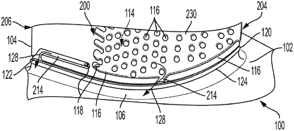
a spar extending radially from the platform, the spar comprising a passageway inside of the spar for a cooling fluid, a pedestal on an outer surface of the spar, and a spar hole configured to direct the cooling fluid from the passageway to the outer surface of the spar;
a fillet located at an intersection of the platform and the spar; and
a coversheet, wherein an inner surface of the coversheet is positioned on the pedestal of the spar, wherein an edge of the coversheet is positioned adjacent to the fillet,
wherein the fillet and/or the coversheet includes a protrusion extending along, and adjacent to, the edge of the coversheet, wherein the pedestal, the outer surface of the spar, and the protrusion define a purge groove,
wherein the protrusion together with the fillet and/or the inner surface of the coversheet along the edge of the coversheet define a purge groove outlet that opens toward the platform, and
wherein the purge groove and the purge groove outlet form a cooling path for the cooling fluid to flow onto the platform; and
wherein the spar hole is positioned adjacent to a leading edge of the spar and is configured to direct the cooling fluid to a cooling channel, wherein the cooling channel directs the cooling fluid to the purge groove.
|