| CPC B65D 51/20 (2013.01) [B29C 45/0001 (2013.01); B29C 45/0081 (2013.01); B65D 71/50 (2013.01); B29K 2023/065 (2013.01); B29L 2031/565 (2013.01); B65D 2251/0018 (2013.01); B65D 2251/0071 (2013.01); B65D 2251/02 (2013.01)] | 16 Claims |
|
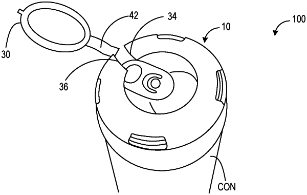
1. A secure container cover for restricting access to an opening of a container comprising:
an integrally molded body including an annular structure and a side wall, wherein
the annular structure includes a central void defined by an intermediate perimeter;
a graspable loop integrally formed with the annular structure is configured to reside within the central void;
a first tear initiation point is formed at a first location where the graspable loop joins the annular structure;
a first thin section extends from the first tear initiation point to a bottom edge of the side wall, the first thin section being defined by a first channel formed in the body of the secure container cover;
a second tear initiation point is formed at a second location where the graspable loop joins the annular structure, the second location being different from the first location;
a second thin section extends from the second tear initiation point to a tear termination point on the side wall, the second thin section being defined by a second channel formed in the body of the secure container cover;
the graspable loop is detachably connected to the annular structure at a bridging section;
the bridging section is configured to break when an upward biasing force is applied to the graspable loop;
the side wall is configured to separate along the first thin section and the second thin section when the graspable loop is pulled away from the body of the secure container cover;
the tear termination point is a protrusion formed on the side wall adjacent to the bottom edge of the side wall; and
the protrusion is configured as a tear barrier that prevents further separation of the side wall along the second thin section.
|