| CPC B64C 27/00 (2013.01) [B64C 2027/8209 (2013.01); B64C 2027/8227 (2013.01); B64C 2027/8254 (2013.01); B64C 2027/8272 (2013.01)] | 19 Claims |
|
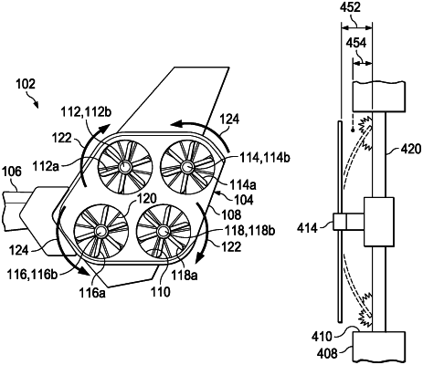
1. A yaw control system coupled to a tailboom of a helicopter, the yaw control system comprising:
a shroud forming a plurality of ducts;
one or more stators disposed in each duct;
a plurality of tail rotors including a clockwise tail rotor and a counterclockwise tail rotor, each tail rotor secured in one of the plurality of ducts by the one or more stators and including a plurality of tail rotor blades; and
a flight control computer implementing a tail rotor blade clearance monitoring module configured to detect a clearance distance between the tail rotor blades and the one or more stators of each duct and an airframe protection command module configured to modify one or more operating parameters of the tail rotors based on the clearance distance;
wherein, the clockwise tail rotor is configured to rotate in a first rotational direction; and
wherein, the counterclockwise tail rotor is configured to rotate in a second rotational direction, the second rotational direction opposite of the first rotational direction.
|