| CPC B61D 15/00 (2013.01) [B66C 5/04 (2013.01); B66C 19/00 (2013.01); B66C 1/22 (2013.01); E01B 29/02 (2013.01)] | 23 Claims |

|
1. A crane apparatus comprising:
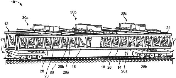
a first truss assembly comprising a first main truss having a longitudinal axis, the first main truss being coupled to a first rail car end assembly;
a second truss assembly comprising a second main truss spaced apart from and extending approximately parallel to the longitudinal axis, the second main truss being coupled to the first rail car end assembly, the first main truss and the second main truss spaced apart from one another to define an interior space; and
an upper gantry assembly rotatably coupled to a first upper support beam of the first truss assembly and to a second upper support beam of the second truss assembly, the upper gantry assembly having a first bridge beam and a second bridge beam spaced apart from one another and extending across the interior space between the first truss assembly and the second truss assembly, the first bridge beam and second bridge beam being slidable parallel to the longitudinal axis within a guide track formed in the first upper support beam of the first truss assembly and a guide track formed in the second upper support beam of the second truss assembly;
wherein a first truss extension is rotationally coupled to a first end of the first main truss and a second truss extension is rotationally coupled to a second end of the first main truss.
|