|
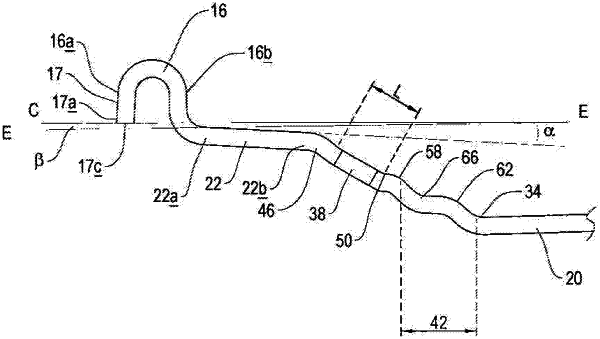
1. A wheel construction for mounting a high load capacity tire, wherein the wheel construction and high load capacity tire are adapted for use in combination with an off road vehicle, the wheel construction including a rim, the rim having an inner flange and an outer flange, each of the inner flange and the outer flange having an arcuate configuration defining a first end and a second end, the first end of each of the inner and outer flange being positioned axially outwardly relative to the second end of the respective flange, the rim further including a central well positioned between the inner flange and the outer flange, a pair of bead seats, one being positioned adjacent each flange, each bead seat having an axially outer end which is connected to a second end of the respective flange by a flange connecting portion, the flange connecting portion including a substantially concave surface and a substantially straight surface extending radially outwardly therefrom, wherein the substantially concave surface and the substantially straight surface are configured to engage surfaces of the high load capacity tire mounted to the rim, wherein the substantially straight surface is adjacent to and adjoins the second end of the respective flange, and each bead seat also having an axially inner end which is connected to one of a pair of side parts, each side part being positioned between the central well and one of the inner flange and outer flange, and connected to the central well by a well connecting portion, the axially outer end of each bead seat being positioned radially outwardly relative to the axially inner end of the respective bead seat, wherein at least one of the inner flange and the outer flange includes an extended portion which extends radially inwardly from the first end of the flange, wherein the extended portion defines a free end that is positioned in its entirety radially inwardly relative to the first end and to the second end of the respective flange and radially inwardly of the location at which the second end of the flange adjoins the substantially straight surface of the flange connecting portion, and wherein at least one of the side parts includes a substantially straight portion and a curved portion, a first end of the straight portion being positioned adjacent the respective bead seat, and connected to the respective bead seat by a curved connecting portion, and a second end of the straight portion being connected to the curved portion of the side part by a first substantially concave surface to provide a first sub-well, and the curved portion of the side part including a second sub-well, which is defined by a pair of convex surfaces, separated by a second concave surface.
|