| CPC B41J 32/00 (2013.01) [B41J 2/325 (2013.01); B41J 3/36 (2013.01); B41J 3/4075 (2013.01); B41J 33/26 (2013.01)] | 9 Claims |

|
1. A tape cassette, comprising:
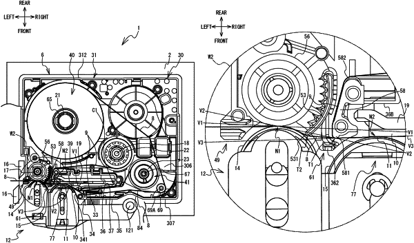
a cassette case including a bottom wall, and a side wall intersecting the bottom wall at a first side in a first direction, the cassette case having a recess recessed from a part of the side wall to a second side in the first direction, the second side in the first direction being opposite to the first side in the first direction, the part of the side wall including an opening, the recess passing through the cassette case in an up-down direction;
a tape roll housed inside the cassette case;
a print tape wound around the tape roll;
a ribbon roll housed inside the cassette case;
an ink ribbon wound around the ribbon roll;
a ribbon winding spool housed inside the cassette case;
an arm portion including a first wall and a second wall, the first wall being a part of the side wall, the second wall facing the first wall and extending upward from the bottom wall, the arm portion extending from a first side in a second direction to a second side in the second direction, the second direction being a direction intersecting the first direction and the up-down direction, the first side in the second direction being opposite to the second side in the second direction, the arm portion including a discharge port at an end, the end being positioned on the second side in the second direction with respect to the opening, the discharge port being configured to discharge the print tape and the ink ribbon conveyed between the first wall and the second wall, the recess being defined by the second wall and a peripheral wall at least;
a roller provided inside the cassette case further to the first side in the second direction than the arm portion, a part of an outer peripheral surface of the roller being exposed to the first side in the first direction of the cassette case, the roller being configured to guide the print tape discharged from the discharge port and in contact with the exposed part of the outer peripheral surface further to the first side in the second direction than the cassette case;
a first protrusion disposed, on a conveyance path of the print tape, at a position between the discharge port of the arm portion and the roller, the first protrusion including a first leading end protruding toward the first side in the first direction, the first leading end being positioned on a first virtual line or being positioned further to the first side in the first direction than the first virtual line, the first virtual line being a line connecting the exposed part of the outer peripheral surface of the roller with a connection portion between the second wall and the peripheral wall, the first protrusion being configured to guide the ink ribbon discharged along the conveyance path from the discharge port to a winding path, the winding path being a path branching from the conveyance path at the first leading end, toward the ribbon winding spool; and
a second protrusion disposed at a position between the first protrusion and the roller in the second direction, the second protrusion including a second leading end protruding toward the first side in the first direction, the second leading end being positioned further to the first side in the first direction than a second virtual line, the second virtual line being a line connecting the exposed part of the outer peripheral surface of the roller with the first leading end of the first protrusion, the second protrusion being configured to guide the print tape discharged from the discharge port to the roller via the second leading end.
|