| CPC A61N 1/36178 (2013.01) [A61B 5/304 (2021.01); A61N 1/36038 (2017.08); A61N 1/36053 (2013.01); A61N 1/36062 (2017.08); A61N 1/36114 (2013.01); A61N 1/36128 (2013.01); A61N 1/36175 (2013.01); A61N 1/37 (2013.01); A61N 1/3704 (2013.01); A61N 1/39622 (2017.08)] | 20 Claims |

|
1. An implantable medical device, comprising:
a power supply module;
a processing unit;
a pulse generator;
an implantable lead system including at least one lead having a plurality of electrodes adapted to stimulate a patient's tissue responsive to instructions generated by the processing unit in association with the pulse generator, the plurality of electrodes including at least one inactive electrode and at least one active electrode;
electrode selection circuitry operative to configure each electrode of the at least one inactive electrode as not selected to stimulate with respect to the patient's tissue and to configure each electrode of the at least one active electrode as selected to stimulate with respect to the patient's tissue, wherein a first inactive electrode of the at least one inactive electrode is not selected to stimulate and thereby configured by the electrode selection circuitry as inactive and a second active electrode of the at least one active electrode is selected to stimulate and thereby configured by the electrode selection circuitry as active;
diagnostic circuitry comprising an analog-to-digital converter (ADC) having a sense input and a reference input; and
switching circuitry operative to selectively couple one or more terminals associated with each electrode to the ADC of the diagnostic circuitry, the switching circuitry including one or more switches for each electrode corresponding to the one or more terminals associated therewith,
wherein the diagnostic circuitry is configured to perform following acts in conjunction with the switching circuitry and the processing unit:
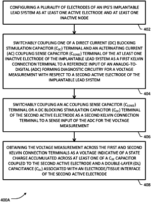
utilize a first direct current (DC) blocking stimulation capacitor (CDC1) terminal coupled to the first inactive electrode or a first alternating current (AC) coupling sense capacitor (CSENSE1) terminal coupled to the first inactive electrode as a first Kelvin connection terminal switchably coupled by the switching circuitry to the reference input of the ADC for a voltage measurement with respect to the second active electrode;
utilize a second AC coupling sense capacitor (CSENSE2) terminal coupled to the second active electrode or a second DC blocking stimulation capacitor (CDC2) terminal coupled to the second active electrode as a second Kelvin connection terminal switchably coupled by the switching circuitry to the sense input of the ADC for the voltage measurement; and
obtain the voltage measurement across the first and second Kelvin connection terminals as a voltage indicative of a charge state accumulated across at least one of a CDC2 capacitor coupled to the CDC2 terminal or a double-layer (DL) capacitance (CDL) associated with an electrode/tissue interface (ETI) of the second active electrode.
|