| CPC A61B 1/00073 (2013.01) [A61B 1/0014 (2013.01); A61B 1/0055 (2013.01); A61B 1/00087 (2013.01); A61B 1/00098 (2013.01); A61B 1/00133 (2013.01); A61B 1/01 (2013.01); A61B 1/018 (2013.01); A61B 1/005 (2013.01); A61B 1/015 (2013.01); A61B 1/07 (2013.01); A61B 1/267 (2013.01); A61B 34/37 (2016.02); A61B 90/361 (2016.02); A61B 2017/00296 (2013.01)] | 13 Claims |

|
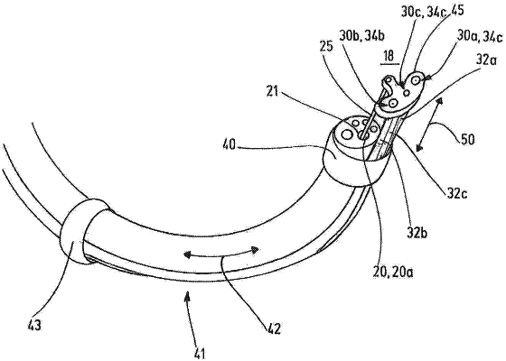
1. A device (10) with an endoscope (11), wherein a shaft (12) of the endoscope (11) encloses a working channel (20) that opens on an outlet side (16) of the shaft (12), the device comprising:
an instrument (30, 30a, 30b, 30c) that is arranged so as to extend next to the shaft (12), wherein the device (10) is configured such that a distal end section (32, 32a, 32b, 32c) of the instrument (30, 30a, 30b, 30c) containing a working section (34, 34a, 34b, 34c) of the instrument (30, 30a, 30b, 30c) is allowed to be moved along the shaft (12) beyond the outlet side (16) of the shaft (12) in order to move the working section (34, 34a, 34b, 34c) of the instrument (30, 30a, 30b, 30c) into a region located distally from (18) the outlet side (16) of the shaft (12) to allow the working section (34, 34a, 34b, 34c) to operate in the region (18); and
a guiding element (25) that extends through the working channel (20) and terminates at a distal end, the guiding element (25) configured to be shifted along a guiding direction (50) defined by the working channel (20) to advance the distal end of the guiding element (25) away from a distal end opening (21) of the working channel (20) and retract the distal end of the guiding element (25) towards the distal end opening (21);
an engagement element (45) comprising a body with a distal facing surface and a proximal facing surface and a through opening extending through the body between the proximal and distal facing surfaces, wherein the through opening is configured to receive the instrument (30, 30a, 30b, 30c) therethrough, wherein the engagement element (45) is releasably connected to the distal end of the guiding element (25) and is configured to be shifted by the guiding element (25) in order to guide the working section (34, 34a, 34b, 34c) of the instrument (30, 30a, 30b, 30c) with the instrument extending through the through opening;
wherein shifting the guiding element (25) distally from the working channel (20) causes the engagement element (45) and the working section (34, 34a, 34b, 34c) of the instrument (30, 30a, 30b, 30c) to be shifted along the guiding direction (50) away from the outlet side (16) of the shaft (12) into the region (18) located distally from the outlet side (16) of the shaft (12);
wherein the guiding element (25) is configured to be disconnected from the engagement element (45) while the distal end of the guiding element (25) and the engagement element (45) are positioned inside a body of a patient by retracting the distal end of the guiding element (25) towards the distal end opening (21);
wherein the guiding element (25) is configured to rotate the engagement element (45) and the working section (34, 34a, 34b, 34c) of the instrument (30, 30a, 30b, 30c) about a longitudinal extension direction (52) of the guiding element (25) and pivot the engagement element (45) and the working section (34, 34a, 34b, 34c) of the instrument (30, 30a, 30b, 30c) relative to a distal end (14) of the shaft (12).
|