| CPC H02M 7/44 (2013.01) [B61C 17/00 (2013.01); H01H 19/12 (2013.01); H01H 19/14 (2013.01); H02M 1/36 (2013.01)] | 18 Claims |

|
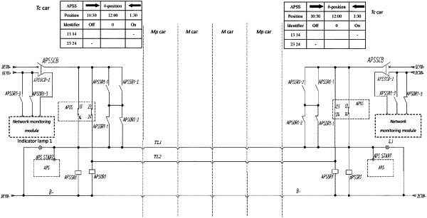
1. A dual start control circuit for auxiliary inverters of a railway vehicle, comprising
two units arranged in a front cab and a rear cab, respectively, and
an APS start train line (TL1) and an APS stop train line (TL2),
wherein the APS start train line (TL1) and the APS stop train line (TL2) are arranged throughout a vehicle,
each unit comprises an auxiliary inverter start switch (APSS), an APS start relay (APSSR1) and an APS stop relay (APSOR1), wherein
the auxiliary inverter start switch (APSS) is a self-reset three-position knob switch and is provided with on-position contacts (13, 14) and off-position contacts (23, 24),
the on-position contacts (13, 14) and the APS start relay (APSSR1) are connected in series to a train power supply,
the off-position contacts (23, 24) and the APS stop relay (APSOR1) are connected in series to the train power supply,
a terminal of the APS start train line (TL1) is connected to a negative pole of the train power supply via an input terminal of the APS start relay (APSSR1) and a load, and
a terminal of the APS stop train line (TL2) is connected to a circuit between the off-position contacts (23, 24) of the auxiliary inverter start switch (APSS) and the APS stop relay (APSOR1); and
normally-open contacts (APSR1-1, APSR1-2) of the APS start relay (APSR1) and normally-closed contacts (APSOR1-1, APSOR1-2) of the APS stop relay (APSOR1) are connected in series between a positive pole of the train power supply and the APS start train line (TL1), and
a start signal interface (APS START) of an auxiliary inverter (APS) is connected to the APS start train line (TL1).
|