| CPC H02K 5/225 (2013.01) [H02K 3/50 (2013.01); H02K 5/22 (2013.01); H02K 11/33 (2016.01); H02K 2203/09 (2013.01)] | 8 Claims |

|
1. A rotating electrical machine, comprising:
a power terminal unit of a rotating electrical machine main body housed in a housing;
a power conversion device fixed to the housing; and
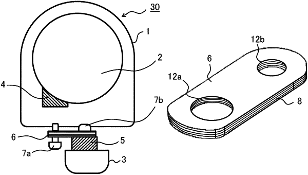
a multilayer bus bar connected to the power terminal unit of the rotating electrical machine main body and a terminal unit of the power conversion device, wherein
the multilayer bus bar has flexibility, and is bent by being connected to the power terminal unit,
the multilayer bus bar includes a first through hole for screw-fastening to the power terminal unit and a second through hole for screw-fastening to the terminal unit of the power conversion device, and
a first gap between the first through hole and a first screw inserted into the first through hole is larger than a second gap between the second through hole and a second screw inserted into the second through hole.
|