| CPC B65D 21/086 (2013.01) [A45F 3/20 (2013.01); A47G 19/2272 (2013.01); A47G 19/2288 (2013.01); B65D 81/3869 (2013.01); A45F 2003/205 (2013.01); A47G 2019/2277 (2013.01)] | 25 Claims |

|
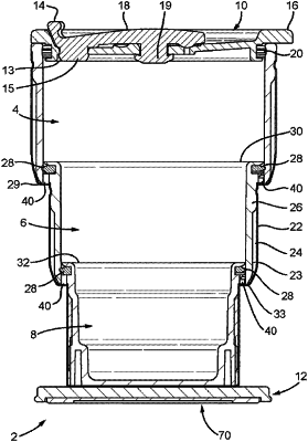
1. A collapsible vessel for containing fluid, the vessel comprising
at least two interconnected tubular sections which are configured to move axially with respect to each other upon application of a substantially axial force thereto, such that the vessel is manipulatable between a collapsed configuration in which the sections are substantially nested to form a tube having a first length and an extended configuration in which the sections form a continuous tube having a second length which is greater than the first length,
wherein each section comprises an inner wall and an outer wall, wherein the inner and outer walls are spaced apart with gas trapped in between the inner and outer wall of a section, and wherein at least one section comprises a circumferential ring which provides a seal between the inner wall of one section and the outer wall of an adjacent section, as the vessel is manipulated between the extended and collapsed configurations,
wherein the vessel comprises locking means configured to be reversibly locked while the vessel is in the extended configuration upon the application of a rotational force to at least one section,
wherein the locking means comprises one or more first locking members disposed on a first section, and one or more second locking members disposed on a corresponding location on an adjacent section, wherein each first locking member is configured to engage with each second locking member, to thereby lock the sections in the extended configuration, upon application of opposing rotational forces to each section,
wherein each first locking member comprises a first moulding, which is attached to, and extends partially around the circumference of the lowermost portion of an inner facing surface of the section to which it is attached, wherein each first moulding comprises a body section from which extends an elongate overhanging finger, wherein the overhanging finger tapers radially inwardly to form a small recess, and tapers radially outwardly to create a terminal lug, and
wherein each second locking member comprises a second moulding, which is attached to, and extends partially around the circumference of the uppermost portion of the outer facing surface of the section to which it is attached.
|