| CPC B60W 30/04 (2013.01) [B60R 21/0132 (2013.01); B60T 8/17554 (2013.01); B60T 13/683 (2013.01); B60W 10/184 (2013.01); B60W 10/30 (2013.01); B62D 37/00 (2013.01); B60R 2021/01306 (2013.01); B60T 2230/03 (2013.01); B60T 2250/03 (2013.01); B60T 2260/09 (2013.01); B60T 2270/88 (2013.01); B60W 2510/182 (2013.01); B60W 2520/14 (2013.01); B60W 2520/18 (2013.01); B60W 2710/182 (2013.01); B60W 2710/30 (2013.01)] | 3 Claims |

|
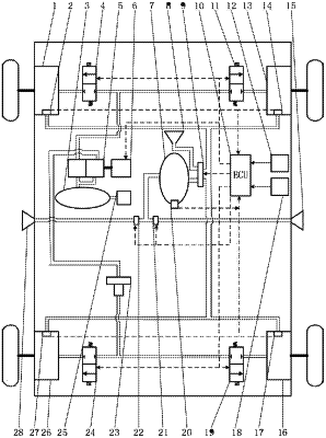
1. An anti-rollover apparatus for heavy-duty vehicles with a pneumatic brake system, comprising an anti-yaw module, an anti-roll module, an electronic control unit (ECU), a yaw velocity sensor, and a vehicle roll angle sensor, wherein
the anti-yaw module comprises a primary air reservoir, a brake valve, a linear actuator, a relay valve, an air compressor, and first to fourth brake units;
the first to fourth brake units are arranged at front left, front right, rear left, and rear right wheels of the heavy-duty vehicle, respectively, and each comprises a switch solenoid valve and a brake chamber, wherein the brake chamber is configured to brake a wheel at a location of the brake chamber;
the brake chambers of the first and second brake units are connected to an output end of a lower cavity of the brake valve via pipes; and the switch solenoid valves of the first and second brake units are arranged in pipes between the brake chambers of the first and second brake units and the output end of the lower cavity of the brake valve, respectively, and are configured to control connection and disconnection of the pipes between the brake chambers of the first and second brake units and the lower cavity of the brake valve;
input ends of an upper cavity and the lower cavity of the brake valve are both connected to an output end of the primary air reservoir via pipes, and an output end of the upper cavity of the brake valve is connected to an input end of the relay valve via a pipe;
an output end of the relay valve is connected to the brake chambers of the third and fourth brake units via pipes, respectively; and the switch solenoid valves of the third and fourth brake units are arranged in pipes between the brake chambers of the third and fourth brake units and the output end of the relay valve, respectively, and are configured to control connection and disconnection of the pipes between the brake chambers of the third and fourth brake units and the relay valve, respectively;
an output shaft of the linear actuator abuts against a stem seat of the brake valve, and is configured to push the stem seat of the brake valve so as to open the brake valve when extended, and when the output shaft of the linear actuator is retracted, the stem seat of the brake valve is reset and automatically closed under the effect of a return spring of the stem seat;
an output end of the air compressor is connected to an input end of the primary air reservoir via a pipe, and is configured to compress air and then feed the compressed air to the primary air reservoir, so as to enable a pressure of the primary air reservoir to be equal to a preset working pressure threshold;
the anti-roll module comprises first to fifth pressure sensors, a secondary air reservoir, a three-position two-way solenoid valve, a bleed nipple, first to second switch valves, and first to second air nozzles;
the first to fifth pressure sensors are arranged in the brake chambers of the first to fourth brake units and the secondary air reservoir, respectively, and are configured to sense pressure values at locations of the pressure sensors and transmit the pressure values to the electronic control unit (ECU);
an input end of the secondary air reservoir is connected to one output end of the three-position two-way solenoid valve via a pipe, and an output end of the secondary air reservoir is connected to the first and second air nozzles via pipes, respectively; and the first and second switch valves are arranged in pipes between the secondary air reservoir and the first and second air nozzles, respectively, and are configured to control connection and disconnection of the pipes between the secondary air reservoir and the first and second air nozzles, respectively;
an input end of the three-position two-way solenoid valve is connected to the brake chambers of the first to fourth brake units via pipes, respectively, and the other output end of the three-position two-way solenoid valve is connected to the bleed nipple via a pipe;
the first and second air nozzles are arranged in the middle of a frame on a located side of the first and second brake units of the heavy-duty vehicle, respectively, and are configured to spray air to the outer side of the heavy-duty vehicle; and the bleed nipple is configured to discharge gases entering the bleed nipple into the air;
the yaw velocity sensor is configured to detect a yaw velocity of a body of the heavy-duty vehicle and transmit the yaw velocity to the electronic control unit (ECU);
the vehicle roll angle sensor is configured to detect the magnitude of a roll angle of the heavy-duty vehicle, and transmit the magnitude of the roll angle to the electronic control unit (ECU); and
the electronic control unit (ECU) is electrically connected to the first to fifth pressure sensors, the switch solenoid valves of the first to fourth brake units, the linear actuator, the three-position two-way solenoid valve, and the first to second switch valves, respectively, and is configured to control the switch solenoid valves of the first to fourth brake units, the linear actuator, the three-position two-way solenoid valve, and the first to second switch valves to operate according to sensing values of the first to fifth pressure sensors.
|