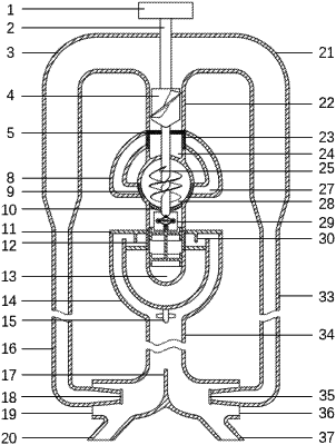
| CPC B03B 11/00 (2013.01) [B03B 5/48 (2013.01)] | 10 Claims |

|
1. A flow self-adjusting type mine diameter grading apparatus applied to tailings recovery, characterized by comprising a driving device, a tailings conveying device, a flow regulating device, and a mine diameter grading device arranged in sequence according to working procedures, wherein
the driving device comprises a motor, and the motor is configured to drive an axial flow impeller and a spiral concentrating wheel to do work through a main shaft connected with the motor;
a tailing water main pipe is arranged above the tailings conveying device, the axial flow impeller is arranged inside the tailing water main pipe, an upper part of the tailing water main pipe is divided into a left tailing water pipe and a right tailing water pipe, the left tailing water pipe is arranged vertically downward via a 90° elbow after horizontally extending a distance, a vertical segment of the left tailing water pipe comprises a shrinking segment, a left ore blowing pipe is arranged below the shrinking segment, the left ore blowing pipe enters a left secondary ore suction pipe horizontally through a 90° elbow after vertically extending a distance, a part of the left ore blowing pipe located inside the left secondary ore suction pipe is a shrinking segment, a left nozzle is arranged at an end of a horizontal segment of the left ore blowing pipe, and a left main ore suction pipe is arranged below the left secondary ore suction pipe; the left secondary ore suction pipe is in communication with the left main ore suction pipe;
the right tailing water pipe is arranged vertically downward via a 90° elbow after horizontally extending a distance, a vertical segment of the right tailing water pipe comprises a shrinking segment, a right ore blowing pipe is arranged below the shrinking segment, the right ore blowing pipe enters a right secondary ore suction pipe horizontally through a 90° elbow after vertically extending a distance, a part of the right ore blowing pipe located inside the right secondary ore suction pipe is a shrinking segment, a right nozzle is arranged at an end of a horizontal segment of the right ore blowing pipe, and a right main ore suction pipe is arranged below the right secondary ore suction pipe; the right secondary ore suction pipe is in communication with the right main ore suction pipe;
a separation baffle is arranged between the left ore suction pipes and the right ore suction pipes;
an ore conveying main pipe connected to the left and right ore suction pipes is arranged above the separation baffle, lower ore conveying branch pipes are arranged above the ore conveying main pipe, an ore separating blade is arranged at the connection between the ore conveying main pipe and the lower ore conveying branch pipes, a top of each of the lower ore conveying branch pipes is connected to a first-level mine diameter storage bin, and the first-level mine diameter storage bin is a hollow cylinder;
a disturbance baffle is connected to an inner upper wall surface of the first-level mine diameter storage bin; a second-level mine diameter storage bin is arranged on an inner side of the first-level mine diameter storage bin, a first-level mine diameter grading plate is arranged between the first-level mine diameter storage bin and the second-level mine diameter storage bin, and a flow regulating valve connected to the main shaft is arranged inside the second-level mine diameter storage bin;
a second-level mine diameter grading plate is arranged above the flow regulating valve, the second-level mine diameter grading plate is embedded below a bin body of a third-level mine diameter storage bin, and the spiral concentrating wheel connected with the main shaft is arranged inside the third-level mine diameter storage bin; a fourth-level mine diameter storage bin is arranged on and connected to an outer side of the third-level mine diameter storage bin, a third-level mine diameter grading plate is arranged between the third-level mine diameter storage bin and the fourth-level mine diameter storage bin, and the third-level mine diameter grading plate is embedded in a bin body of the third-level mine diameter storage bin; upper ore conveying branch pipes are connected to an outer upper side of the fourth-level mine diameter storage bin, a top of each of the upper ore conveying branch pipes is connected with a fifth-level mine diameter storage bin, a fourth-level mine diameter grading plate is arranged between the upper ore conveying branch pipes and the fifth-level mine diameter storage bin, and the fourth-level mine diameter grading plate is embedded in a bin body of the fifth-level mine diameter storage bin; and a fifth-level mine diameter grading plate is arranged at a top of the fifth-level mine diameter storage bin.
|