| CPC H02M 1/0009 (2021.05) [G01R 15/09 (2013.01); H02M 3/156 (2013.01); H02M 7/12 (2013.01)] | 11 Claims |

|
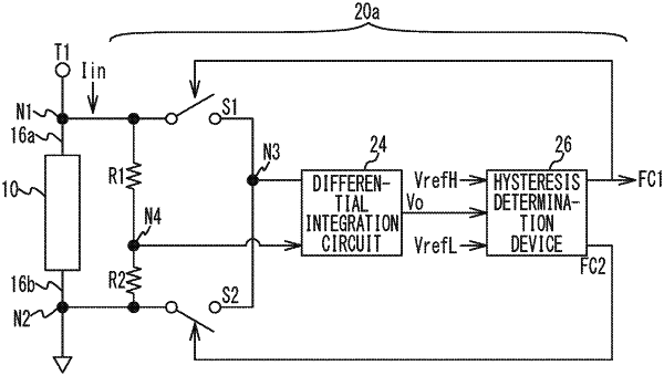
1. A current sensor comprising:
a resistance element that is connected between a first terminal and a second terminal, enters a high-resistance state when an absolute value of a current flowing between the first terminal and the second terminal is within a first range, and changes to a low-resistance state in which a resistance value is lower than that in the high-resistance state when the absolute value of the current exceeds the first range; and
a circuit that senses a value of the current based on at least one of voltages of the first terminal and the second terminal;
wherein the resistance element is in the high-resistance state when a temperature of the resistance element is within a first temperature range, and the resistance element is in the low-resistance state when the temperature is higher than the first temperature range.
|