| CPC G02B 6/4269 (2013.01) [G02B 6/4256 (2013.01); G02B 6/428 (2013.01); G02B 6/4284 (2013.01); G02B 6/4246 (2013.01)] | 18 Claims |

|
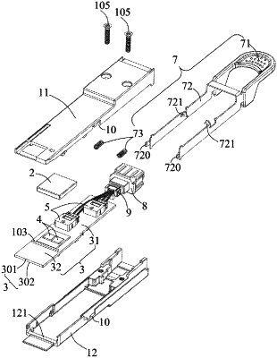
1. An optical electrical connector, comprising:
a casing comprising an electrical port and an optical port, the electrical port having a plurality of gold fingers, the optical port being disposed opposite to the electrical port along a first direction, a receiving space being defined by the casing between the electrical port and the optical port;
a printed circuit board extending longitudinally along the first direction, the printed circuit board comprising a main body portion located in the receiving space and a front end portion exposed in the electrical port;
at least one electronic chip and at least one photoelectric conversion component being accommodated in the receiving space, the electronic chip and the photoelectric conversion component not only being disposed on the printed circuit board but also electrically connected to the printed circuit board;
a heat sink device being accommodated in the receiving space, the heat sink device being disposed on the casing and facing the electronic chip for conducting the heat accumulated on the electronic chip to the outside of the optical electrical connector through the casing; and
at least one electromagnetic wave absorbing element, wherein the casing comprises a first casing and a second casing, the first casing and the second casing are fastened together in a second direction perpendicular to the first direction, the receiving space is formed by the first casing and the second casing; wherein the first casing comprises a first extension portion protruding toward the second casing, the second casing comprises a second extension portion protruding toward the first casing, the first extension portion and the second extension portion are aligned in the second direction for adhering the electromagnetic wave absorbing element.
|