| CPC F23R 7/00 (2013.01) [F02C 5/02 (2013.01); F23R 3/16 (2013.01); F23R 3/286 (2013.01); F23R 3/425 (2013.01)] | 18 Claims |

|
6. A rotating detonation combustor comprising:
a combustion chamber configured for a rotating detonation process to produce a flow of combustion gas;
an air plenum configured to contain a volume of air, the air plenum defined by a first wall, a second wall having an air inlet therethrough for providing a flow of air into the air plenum, and a third wall coupling a first end of the first wall and a first end of the second wall;
a first sidewall extending from the first wall to the combustion chamber and a second sidewall extending from the second wall to the combustion chamber, the first sidewall and the second sidewall defining a flow passage therebetween, said flow passage coupled in flow communication between said combustion chamber and said air plenum and configured to channel an airflow from said air plenum into the combustion chamber;
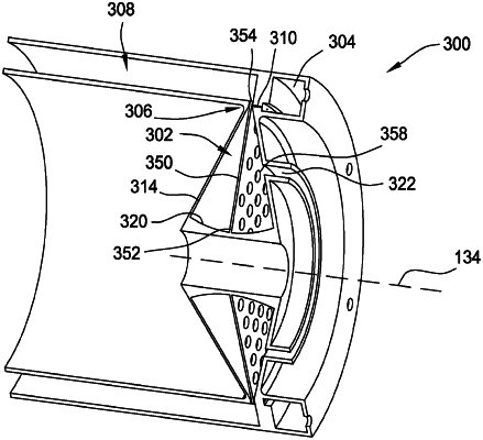
an air flow splitter wall arranged within the air plenum, the air flow splitter wall having a first end extending from the third wall of the air plenum and a second end extending at least partially within said flow passage between said first sidewall and said second sidewall, wherein the air flow splitter wall comprises a plurality of openings positioned within the air plenum upstream of the flow passage, the plurality of openings enabling airflow from the air inlet through the air flow splitter wall to fill the air plenum;
a plurality of fuel mixing mechanisms coupled to at least one of said air flow splitter wall, said first sidewall, or said second sidewall; and
a plurality of fuel inlets extending through at least one of the first sidewall or the second sidewall and coupled in flow communication with said flow passage and configured to channel a fuel flow into said flow passage, wherein said plurality of fuel mixing mechanisms are configured to mix said airflow and said fuel flow within said combustion chamber.
|