| CPC F16C 32/0614 (2013.01) [F16M 11/043 (2013.01)] | 8 Claims |

|
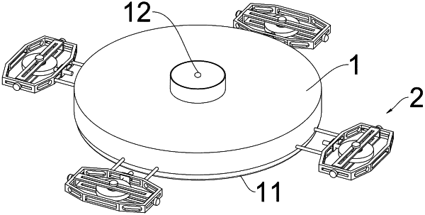
1. A magnetic preloading air bearing, comprising an air floating substrate (1), wherein a plurality of preloading assemblies (2) are disposed around the air floating substrate (1), an annular air floating structure (11) extends and protrudes at one side of the air floating substrate (1), an air inlet channel (12) penetrates and extends at another side of the air floating substrate (1), a shunt assembly (3) is disposed inside the air floating substrate (1), a side edge of the shunt assembly (3) is disposed corresponding to an inner side of the air floating structure (11), the air inlet channel (12) is disposed corresponding to the shunt assembly (3), a flow-buffering assembly (4) is disposed at an end of the air inlet channel (12), and the flow-buffering assembly (4) is disposed in cooperation with the shunt assembly (3);
the shunt assembly (3) comprises an annular filter sleeve (31), a first base ring (32) is coaxially spaced outside the annular filter sleeve (31), a second base ring (33) is coaxially spaced outside the first base ring (32), the second base ring (33) is fixedly disposed on the air floating substrate (1), and a circumferential direction of the second base ring (33) is disposed corresponding to the inner side of the air floating structure (11);
the plurality of preloading assemblies (2) are connected to the air floating substrate (1) through a fixing rod (22);
each of the plurality of preloading assemblies (2) comprises a magnet (21), a first frame (23) and a second frame (24), the magnet (21) is received in the second frame (24), the second frame (24) is received in the first frame (23), a plane of the first frame (23) is perpendicular to a plane of the second frame (24), a first sliding groove (231) is disposed at opposite sides of one side of the first frame (23), respectively, a fixing sleeve (232) is slidably and cooperatively disposed on the first sliding groove (231), a sliding rod (233) penetrates through the fixing sleeve (232), and an end of the sliding rod (233) is connected to the magnet (21); and
a limit plate (241) is disposed at two sides of the second frame (24), respectively, a second sliding groove (242) is disposed at two opposite sides of another side of the first frame (23), respectively, the second sliding groove (242) is disposed in cooperation with the limit plate (241), a limit column (211) is disposed at both sides of the magnet (21), respectively, a third sliding groove (212) is disposed at both sides of the second sliding groove relative to the magnet (21), respectively, the third sliding groove (212) is disposed in cooperation with the limit column (211), and the fixing rod (22) is connected to the first frame (23).
|