| CPC D06F 35/006 (2013.01) [D06F 21/02 (2013.01); D06F 37/06 (2013.01); D06M 23/08 (2013.01)] | 44 Claims |

|
1. An apparatus for use in the treatment of substrates with a solid particulate material, said apparatus comprising a housing having mounted therein a rotatably mounted drum having an inner surface and an end wall and access means for introducing said substrates into said drum, wherein
(a) said drum comprises storage means for storage of said solid particulate material; and
(b) said drum comprises a first collecting flow path to facilitate flow of said solid particulate material from the interior of said drum to said storage means when said drum rotates in a first collecting direction,
characterised in that said drum comprises a second collecting flow path to facilitate flow of said solid particulate material from the interior of said drum to said storage means when said drum rotates in a second collecting direction, wherein said second collecting direction is in the opposite rotational direction to said first collecting direction, and wherein said first collecting flow path and said second collecting flow path are different flow paths; and
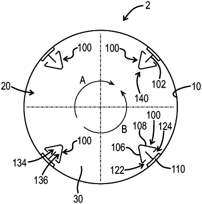
wherein said drum has a first elongate protrusion located on said inner surface of said drum wherein said first elongate protrusion extends in a direction away from said end wall, wherein said first elongate protrusion has an end proximal to the end wall and an end distal to the end wall, wherein said first elongate protrusion comprises said first collecting flow path and further comprises a first collecting aperture, wherein said first collecting aperture defines the start of said first collecting flow path; and
wherein said first collecting aperture is disposed in a first side of said first elongate protrusion, wherein said first side of said first elongate protrusion is the leading side of said first elongate protrusion during rotation of the drum in said first collecting direction; and
wherein said first elongate protrusion further comprises said second collecting flow path and a second collecting aperture, wherein said second collecting aperture defines the start of said second collecting flow path; and
wherein said second collecting aperture is disposed in a second side of said first elongate protrusion, wherein said second side of said first elongate protrusion is the leading side of said first elongate protrusion during rotation of the drum in said second collecting direction.
|