| CPC A61F 2/4425 (2013.01) [A61F 2/4455 (2013.01); A61F 2002/30281 (2013.01); A61F 2002/30433 (2013.01); A61F 2002/443 (2013.01)] | 20 Claims |

|
1. An expandable implant movable between a contracted position and an expanded position, comprising:
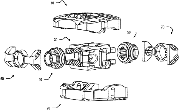
an expandable body having a longitudinal axis extending through a center of the expandable body from a proximal end to a distal end in a proximal-to-distal direction, the expandable body extending from a first lateral side to a second lateral side in a widthwise direction, and extending from a superior end to an inferior end in a vertical direction, the expandable body being defined by a superior endplate and an inferior endplate opposite the superior endplate,
the superior endplate including a first outside surface and a first inside surface opposite the first outside surface, the first inside surface including first proximal ramps and first distal ramps disposed opposite the first proximal ramps,
the inferior endplate including a second outside surface and a second inside surface opposite the second outside surface, the second inside surface including second proximal ramps and second distal ramps disposed opposite the second proximal ramps;
a support block coupled to the superior endplate and the inferior endplate, the support block having a proximal screw guide and a distal screw guide opposite the proximal screw guide,
a proximal set screw rotatably supported by the proximal screw guide and a distal set screw rotatably supported by the distal screw guide;
a proximal wedge including first superior ramped surfaces and first inferior ramped surfaces, the proximal wedge being coupled to the proximal set screw;
a distal wedge including second superior ramped surfaces and second inferior ramped surfaces, the distal wedge being coupled to the distal set screw; and
at least one eyelet disposed on the proximal end of the expandable body;
wherein:
in the contracted position the proximal wedge and the distal wedge are disposed in a medial position of the body,
in a first expanded position a spacing between the superior and inferior endplates at a proximal side is greater than a spacing between the superior and inferior endplates at the proximal side in the contracted position, in the first expanded position the proximal wedge contacts the the first proximal ramps and the second proximal ramps and is disposed proximate the proximal side, and
in a second expanded position a spacing between the superior and inferior endplates at a distal side is greater than a spacing between the superior and inferior endplates at the distal side in the contracted position, in the second expanded position the distal wedge contacts the first distal ramps and the second distal ramps and is disposed proximate the distal side with respect to the medial position.
|