| CPC H04N 25/75 (2023.01) [H04N 25/53 (2023.01); H04N 25/745 (2023.01); H04N 25/771 (2023.01)] | 20 Claims |

|
1. A pixel circuit, comprising:
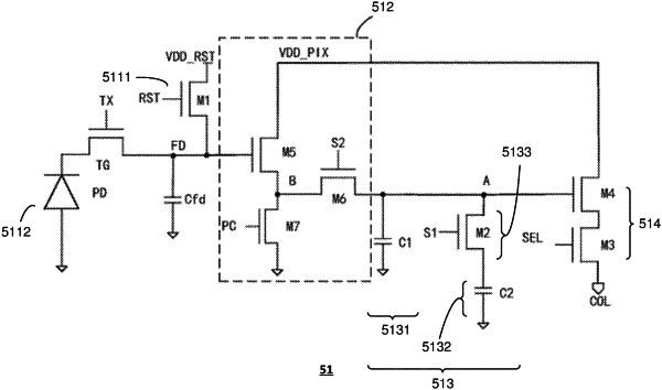
a source module, comprising a photosensitive unit and a reset unit configured to reset the photosensitive unit, wherein the source module is configured to output non-simultaneously a reference signal indicative of a reset level and an electrical signal indicative of incident light received by the photosensitive unit,
a sampling module, comprising a first sampling unit, a second sampling unit and a sampling switch,
a first switch module configured to be electrically coupled between the source module and the sampling module,
a second switch module configured to be electrically coupled between the sampling module and a bus,
wherein the first sampling unit is configured to be electrically coupled to the first switch module and the second switch module, the second sampling unit is configured to be electrically coupled to the first switch module and the second switch module by the sampling switch, and the first sampling unit and the second sampling unit are configured to sample and store the signals from the source modules individually,
wherein the first sampling unit comprises a first capacitor that is directly coupled with the first switch module and a first reference voltage, respectively, and the second sampling unit comprises a second capacitor coupled between the sampling switch and a second reference voltage, and
wherein the sampling switch is provided outside an electrical path between the first sampling unit and the first switch module, and/or outside an electrical path between the first sampling unit and the second switch module.
|